Steel plate cutting equipment

A technology for cutting equipment and steel plates, applied in the direction of metal sawing equipment, metal processing equipment, maintenance and safety accessories, etc., can solve the problems of steel plate blackening, not giving a good solution, bending, etc., to achieve the solution of bending Effect

Active Publication Date: 2020-11-27
泰兴市蚁克搬运设备有限公司
View PDF7 Cites 1 Cited by
  • Summary
  • Abstract
  • Description
  • Claims
  • Application Information

AI Technical Summary

Problems solved by technology

[0004] A kind of steel plate cutting in the above scheme, although the steel production efficiency and product quality are improved to a certain extent, but when the cutting wheel is running, it is impossible to cool down and clean the cutting wheel, and the steel plate caused by sparks generated during the cutting process cannot The problems of blackening and bending due to force did not give a good solution

Method used


Image

  • Steel plate cutting equipment
  • Steel plate cutting equipment
  • Steel plate cutting equipment

Examples


Embodiment Construction

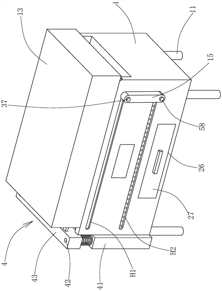
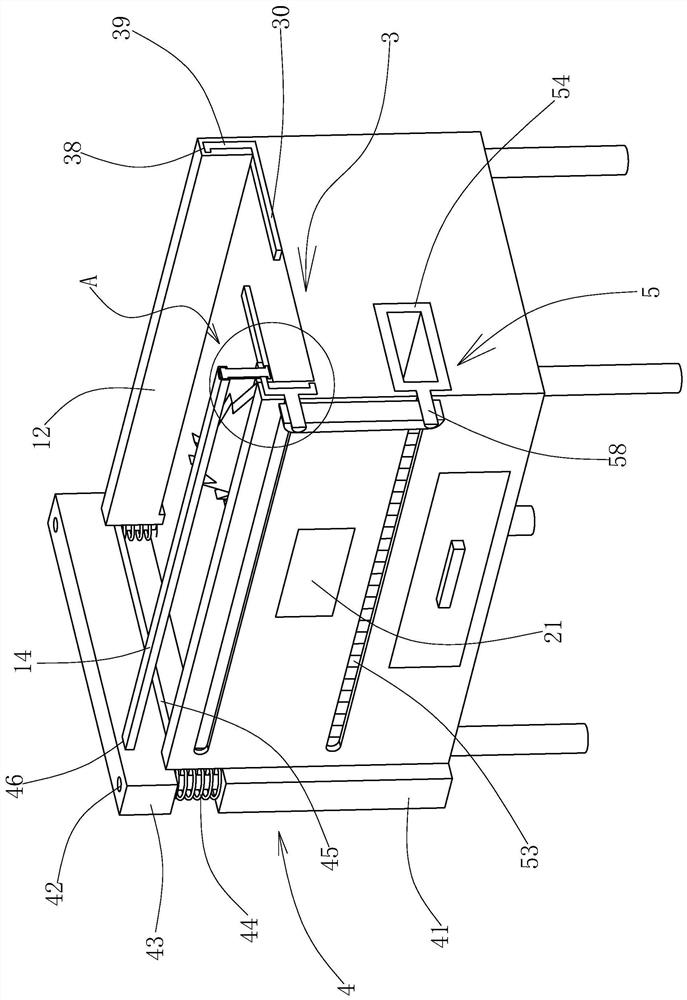
[0022] like figure 1 , figure 2 , image 3 , Figure 4 , Figure 5 As shown, a steel plate cutting equipment includes an operating table 1 with a support rod 11 at the lower end, and is characterized in that: the operating table 1 is provided with a cutting device 2, and both sides of the cutting device 2 are symmetrically provided with mounting rods 12, and the mounting rods 12 One side is movably connected with the side of the protective cover 13, and the mounting rod 12 is provided with a steel plate clamping device 3, and the steel plate clamping device 3 is connected with a steel plate processing device 4 through a pressure bar 14, and the steel plate processing device 4 is installed in a place far away from the protective cover. 13 and the side of the connection position of the pole 11, the side of the steel plate clamping device 3 is also connected with the cooling device 5 through the push rod 15, and the protective cover 13 is movably installed on the side of the ...


PUM


Abstract

The invention provides steel plate cutting equipment which comprises an operating table provided with supporting rods at the lower end. The steel plate cutting equipment is characterized in that a cutting device is arranged on the operating table, mounting bars are symmetrically mounted on two sides of the cutting device, one sides of the mounting bars are movably connected to one side of a protecting hood in a fit manner, a steel plate clamping device is arranged on the mounting bars, the steel plate clamping device is connected to a steel plate treatment device through a pressure bar, and one side of the steel plate clamping device is further connected to a cooling device through a push rod. The invention provides the steel plate cutting equipment. By adopting the pressure bar to connectthe steel plate clamping device and the steel plate treatment device and adopting the push rod to connect the steel plate clamping device and the cooling device, the steel plate clamping device, thesteel plate treatment device and the cooling device are linked, so that the devices are matched in use when the cutting device cuts a steel plate to cool the steel plate and clean scraps, and therefore, the steel plate is cleaned and planished.

Description

technical field [0001] The invention belongs to the technical field of building decoration and steel material cutting, and in particular relates to a steel plate cutting equipment. Background technique [0002] In building construction, steel plates of different widths are usually required. Therefore, steel plate cutting equipment is one of the indispensable equipment in building construction. In the prior art, steel plates are usually cut by installing a cutting wheel on the operating table. , although the structure is simple, it cannot solve the function of cooling and cleaning the cutting wheel, which will easily cause the temperature of the cutting wheel to be too high when cutting, and it is easy to stick waste chips, which will further affect the cutting effect and service life of the cutting wheel. [0003] For example, a Chinese patent document discloses a steel plate cutting machine, [Application No.: 201711498021.0], which includes a horizontal movement mechanism...

Claims


Application Information

Patent Timeline
Patent Type & Authority Applications(China)
IPC IPC(8): B23D45/00B23D47/00B23Q11/10
CPCB23D45/00B23D47/00B23Q11/10
Inventor 梁伟豪陈强
Owner 泰兴市蚁克搬运设备有限公司
Why Eureka
Try Eureka