Annealing furnace for enamelled wire production

An annealing furnace and enameled wire technology, which is applied to furnaces, furnace types, heat treatment furnaces, etc., can solve the problems of inability to anneal multiple enameled wires, the volume of the annealing device becomes larger, and the burden on the electric heating tube is increased, so as to prevent the cooling effect from being poor and prevent the The effect of grease adhering to the surface of enameled wire and preventing oxidation

Pending Publication Date: 2020-11-27
白建生
View PDF11 Cites 3 Cited by
  • Summary
  • Abstract
  • Description
  • Claims
  • Application Information

AI Technical Summary

Problems solved by technology

[0003] The enameled wire needs to be annealed during production. The traditional annealing furnace generally adopts the heating method of the electric heating tube, and then passes the enameled wire through the electric heating tube, and then transfers the heat to the enameled wire to realize annealing. When the enameled wire is in production, the annealing temperature It should not be too high or too low, so the length of the electric heating tube must be lengthened, which will increase the volume of the annealing device, and it is impossible to anneal multiple enameled wires at one time, which will increase the burden on the electric heating tube, and the enameled wire During annealing, due to the large amount of grease attached to the outer surface of the enameled wire, the grease is evaporated during annealing, and some evaporates into the air, but a part of the grease enters the water tank and adheres to the surface of the cooling water tank when it is cold. A large amount of grease has accumulated in the cooling water tank. When the enameled wire enters the cooling water tank, tiny grease is attached to the outer surface of the enameled wire, which affects the quality of subsequent painting.

Method used


Image

  • Annealing furnace for enamelled wire production
  • Annealing furnace for enamelled wire production
  • Annealing furnace for enamelled wire production

Examples


Embodiment Construction

[0017] The following will clearly and completely describe the technical solutions in the embodiments of the present invention with reference to the accompanying drawings in the embodiments of the present invention. Obviously, the described embodiments are only some, not all, embodiments of the present invention. Based on the embodiments of the present invention, all other embodiments obtained by persons of ordinary skill in the art without making creative efforts belong to the protection scope of the present invention.

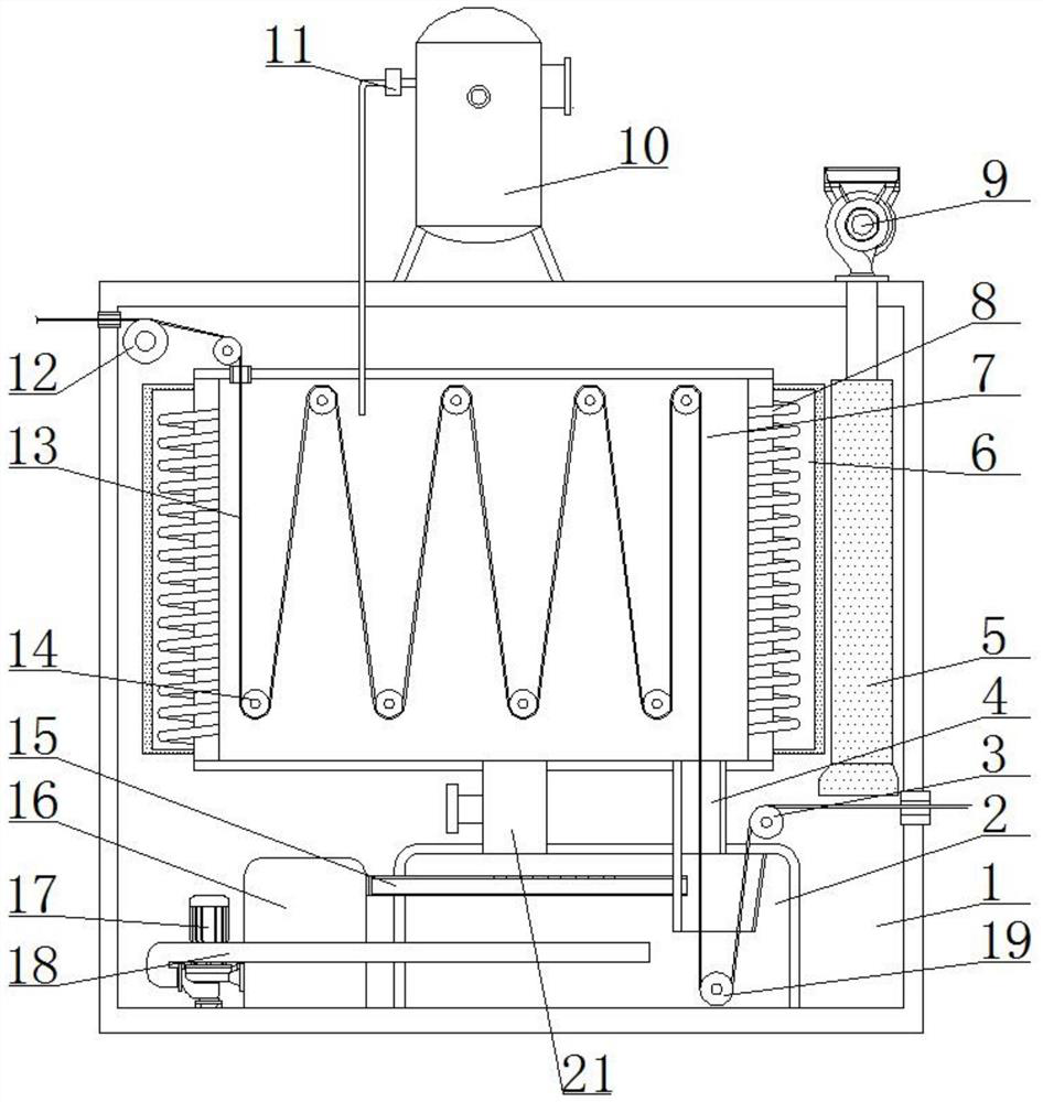
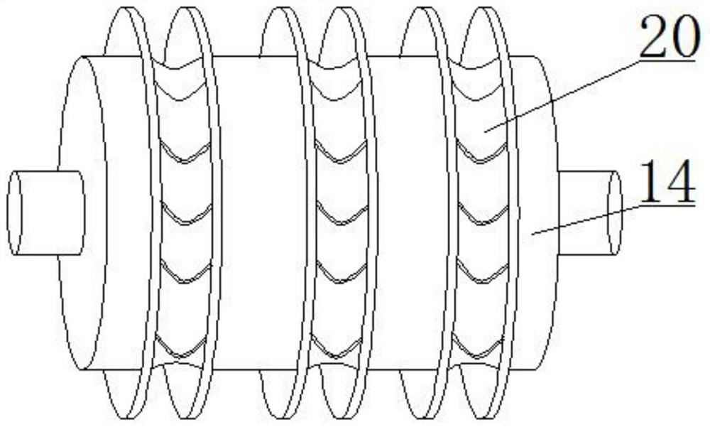
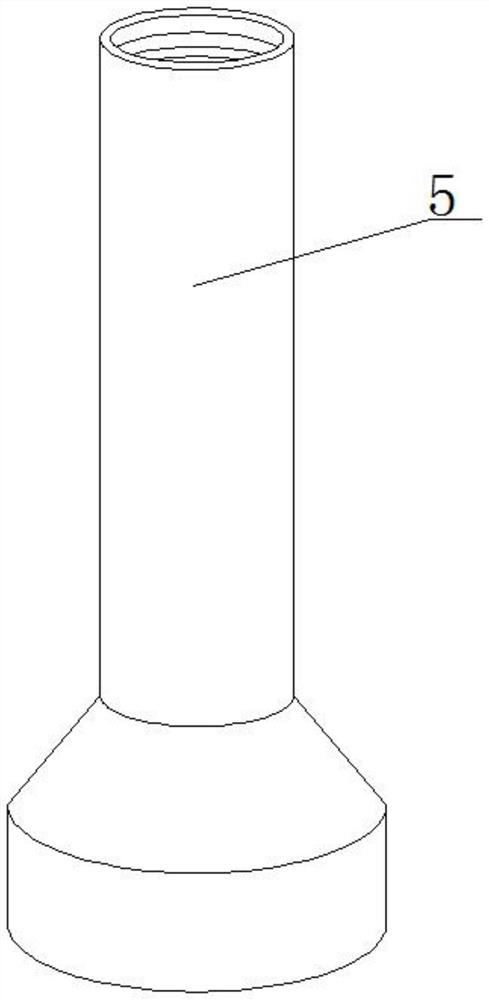
[0018] see Figure 1-3 , an annealing furnace for enameled wire production, comprising an annealing furnace shell 1, a cooling water tank 2 is fixedly installed at the bottom of the inner cavity of the annealing furnace shell 1, and a first winding roller 19 is movable installed inside the cooling water tank 2, and inside the annealing furnace shell 1 The bottom of the cavity is located on the left side of the cooling water tank 2, and a grease separation box ...


PUM


Abstract

The invention relates to the technical field of enamelled wire production, and discloses an annealing furnace for enamelled wire production. The annealing furnace comprises an annealing furnace shell,a cooling water tank is fixedly installed at the bottom of an inner cavity of the annealing furnace shell, a first winding roller is movably installed inside the cooling water tank, a grease separation box is fixedly installed on a position, located on the left side of the cooling water tank, at the bottom of the inner cavity of the annealing furnace shell, a circulating pump is fixedly installedon the position, located on the left side of the grease separation box, at the bottom of the inner cavity of the annealing furnace shell, and the input end of the circulating pump fixedly communicates with the left side face of the grease separation box. According to the annealing furnace for enamelled wire production, an original electric heating pipe type annealing furnace is changed into an existing electromagnetic induction type annealing device, annealing operation can be carried out on a plurality of enamelled wires at the same time, meanwhile, the power of the annealing device does notneed to be increased; and and through the arranged multiple internal wire rollers, the length of the annealed enameled wires located inside can be increased, and the size of the annealing furnace does not need to be increased, so that a large amount of space is saved.

Description

technical field [0001] The invention relates to the technical field of enameled wire production devices, in particular to an annealing furnace for enameled wire production. Background technique [0002] Enameled wire is a main variety of winding wire, which is composed of conductor and insulating layer. The bare wire is annealed and softened, and then painted and baked for many times. The product is not easy. It is affected by factors such as raw material quality, process parameters, production equipment, and environment. Therefore, the quality characteristics of various enameled wires are different, but they all have four major properties: mechanical properties, chemical properties, electrical properties, and thermal properties. . [0003] The enameled wire needs to be annealed during production. The traditional annealing furnace generally adopts the heating method of the electric heating tube, and then passes the enameled wire through the electric heating tube, and then t...

Claims


Application Information

Patent Timeline
Patent Type & Authority Applications(China)
IPC IPC(8): C21D9/60C21D9/573C21D1/26
CPCC21D1/26C21D9/5732C21D9/60Y02P10/25
Inventor 白建生
Owner 白建生
Why Eureka
Try Eureka