
Thread-knotting-preventing thread releasing device for knitting machine

A technology for a thread pay-off device and a knitting machine, which is applied in the direction of thread-pulling hooks for sewing machines, knitting fabrics, sewing machine components, etc., can solve the problems of affecting production, loose sewing threads, mechanical failures, etc., and achieve the effect of convenient transportation.

Inactive Publication Date: 2020-11-27
泰安科鼎特工贸有限公司
View PDF6 Cites 0 Cited by
  • Summary
  • Abstract
  • Description
  • Claims
  • Application Information

AI Technical Summary

Problems solved by technology

[0003] Existing knitting machines use anti-knotting thread unwinding devices and sewing coil disassembly and assembly. It is necessary to remove the nut at the end of the fixed shaft and use tools to replace the sewing coil, which is inconvenient for quick replacement. At the same time, the sewing thread is entangled in a large area On the outer surface of the sewing coil, the sewing thread shakes from side to side during the conveying process and is separated from the conveying roller, causing mechanical failure. In addition, the sewing coil is slidably sleeved on the outer surface of the fixed shaft, and the sewing thread will loosen during the conveying process, affecting post production

Method used


Image

  • Thread-knotting-preventing thread releasing device for knitting machine
  • Thread-knotting-preventing thread releasing device for knitting machine
  • Thread-knotting-preventing thread releasing device for knitting machine

Examples


Embodiment Construction

[0032] The following will clearly and completely describe the technical solutions in the embodiments of the present invention in conjunction with the accompanying drawings in the embodiments of the present invention; obviously, the described embodiments are only part of the embodiments of the present invention, not all embodiments, based on The embodiments of the present invention and all other embodiments obtained by persons of ordinary skill in the art without making creative efforts belong to the protection scope of the present invention.

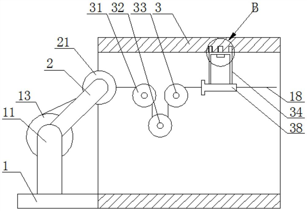
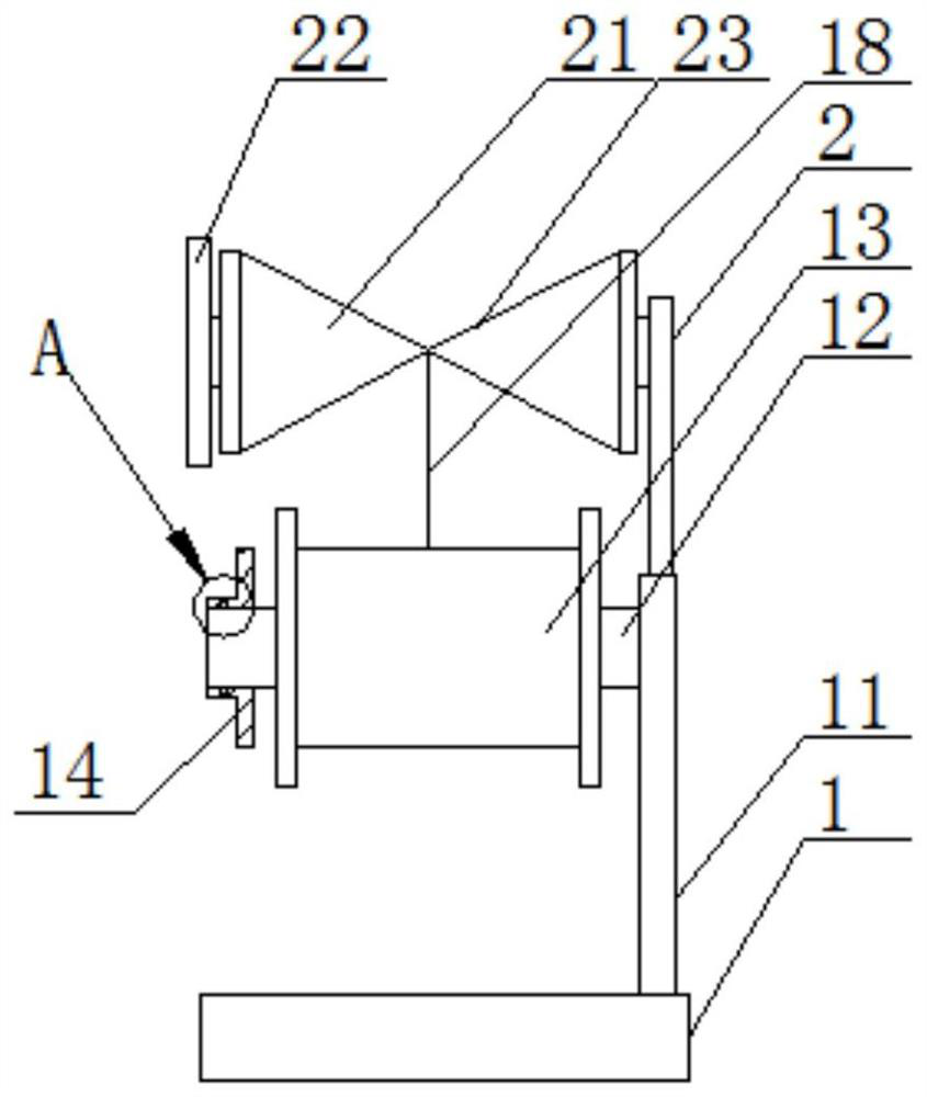
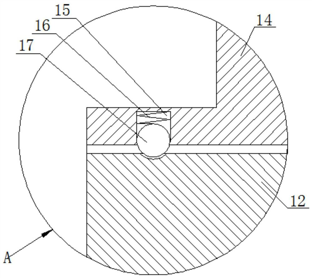
[0033] see Figure 1-5 , a kind of pay-off device for the anti-thread knotting of a knitting machine, comprising a base 1, the upper end surface of the base 1 is fixedly welded with a column 11, the upper side of the column 11 is fixedly welded with a fixed shaft 12, and the outer side of the fixed shaft 12 is slidingly sleeved with The sewing coil 13, the left side of the fixed shaft 12 is slidingly sleeved with a retaining ring 14, the...


PUM


Abstract

The invention discloses a thread-knotting-preventing thread releasing device for a knitting machine, and belongs to the field of thread releasing devices. The thread releasing device comprises a base,and a stand column is fixedly welded to the upper end face of the base. According to the thread-knotting-preventing thread releasing device for the knitting machine, a check ring moves leftwards, a small ball is driven to be separated from clamping of a fixed shaft ball groove, and the check ring is conveniently and rapidly disassembled and assembled; a rolling wheel is in sliding connection withthe upper end of the right side of a connecting frame, the moving direction of a sewing thread is conveniently guided, and the circumstance that the sewing thread shakes and is separated from conveying of the rolling wheel, and mechanical faults are caused is prevented; through the design of an inclined face, the sewing thread can slide towards the middle of the rolling wheel, and conveying of the sewing thread is facilitated; through the cooperative design of a first rolling wheel, a second rolling wheel and a third rolling wheel, the sewing thread can be in a tightened state, and the circumstance that the sewing thread is loosened, and later production is affected is prevented; a clamping block is fastened and clamped to a clamping groove, a screw is tightened clockwise, a supporting frame can be fixed, and rotation of the supporting frame is prevented; and through the design of a guide cylinder, the moving direction of the sewing thread can be guided, and the circumstance that thesewing thread shakes substantially, and production is affected is prevented.

Description

technical field [0001] The invention relates to the field of pay-off devices, in particular to a pay-off device for knitting machines used to prevent thread knotting. Background technique [0002] The types of raw materials applicable to the knitting machine are: nylon multifilament (thread), polypropylene filament (thread), polypropylene, polyester, nylon, PP, low elastic, high elastic, cotton yarn (thread), pearl light, leather, mixed, etc. Knitting machines can be divided into sweater knitting machines, glove knitting machines, steel wire knitting machines, wire mesh knitting machines, straw rope knitting machines, elastic band knitting machines, plastic mesh bag knitting machines, etc. [0003] Existing knitting machines use anti-knotting thread unwinding devices and sewing coil disassembly and assembly. It is necessary to remove the nut at the end of the fixed shaft and use tools to replace the sewing coil, which is inconvenient for quick replacement. At the same time, ...

Claims


Application Information

Patent Timeline
Patent Type & Authority Applications(China)
IPC IPC(8): D04C3/02D05B53/00D05B47/00
CPCD04C3/02D05B47/00D05B53/00
Inventor 杨云
Owner 泰安科鼎特工贸有限公司
Learn More