Cleaning method based on glass fiber cloth impurities
A technology of glass fiber cloth and cleaning method, which is applied in the direction of separation method, chemical instrument and method, mechanical cleaning, etc., can solve the problems of reducing effect, increasing labor intensity, reducing the service life of the structure, etc., to achieve rapid cleaning, improve adsorption effect, The effect of improving the adsorption capacity
- Summary
- Abstract
- Description
- Claims
- Application Information
AI Technical Summary
Problems solved by technology
Method used
Image
Examples
Embodiment 1
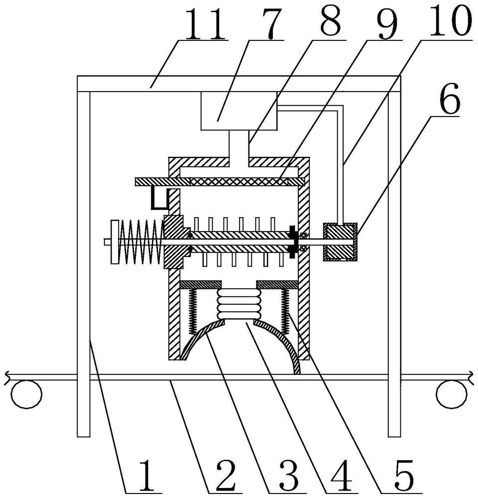
[0046] Such as Figure 1 to Figure 7 Shown, the present invention comprises the following steps:
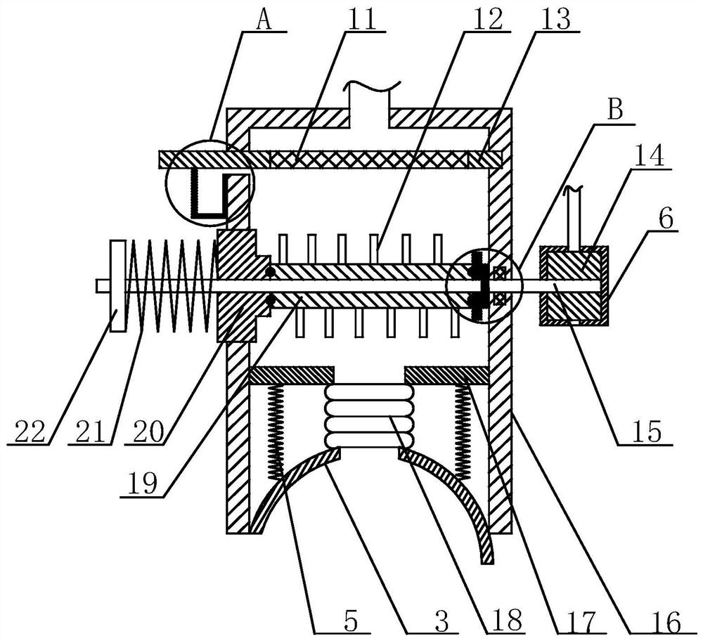
[0047] 1) Place the glass fiber cloth 2 on the drive roller under the box body 16, and under the action of the first elastic member 5, press the arc-shaped baffle plate 3 on the surface of the glass fiber cloth 2;
[0048] 2) The drive roller blocks impurities attached to the surface of the glass fiber cloth 2 in the arc-shaped groove of the baffle 3 during the process of driving the glass fiber cloth 2 to move;
[0049] 3) The suction generated by the exhaust fan 7 sucks the impurities in the baffle 3 into the box 16 through the bellows 18;
[0050] 4) The gas exhausted by the exhaust fan 7 enters the fixed box 6 through the exhaust pipe 10, and drives the movable piece 14 in the fixed box 6 to rotate, thereby driving the movable shaft 15 to rotate in the box body 16;
[0051] 5) When the movable shaft 15 rotates in the casing 16, it drives the movable cylinder 19 to rotate to...
Embodiment 2
[0056] On the basis of Embodiment 1, the filter assembly 9 includes a horizontal plate 13 and a filter screen 11, the horizontal plate 13 is detachably connected with the box body 16, the horizontal plate 13 is provided with a third through hole, and the filter The mesh 11 is located inside the through hole.
Embodiment 3
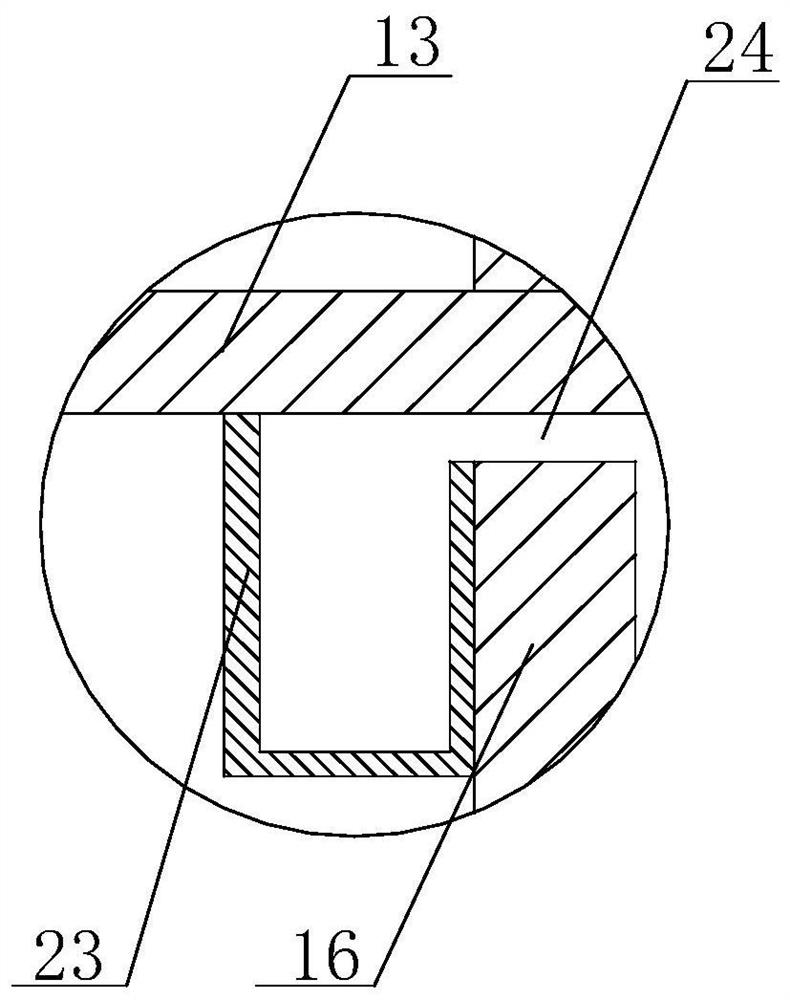
[0058] On the basis of Embodiment 1, one side of the inner wall of the box body 16 is provided with a groove matching the horizontal plate 13, and the other side of the inner wall of the box body 16 is also provided with a fourth channel with a thickness greater than that of the horizontal plate 13. Holes 24, one end of the horizontal plate 13 is inserted into the groove through the fourth through hole 24, and the other end is located outside the box body 16;
[0059] The outer side of the box body 16 is also provided with a dust box 23 with an open top structure, the dust box 23 is located on the top of the horizontal plate 13, and the side wall of the dust box 23 in contact with the box body 16 is provided with a gap , and the gap is flush with the fourth through hole 24 .
PUM
 Abstract
Description
Claims
Application Information
 - R&D
- Intellectual Property
- Life Sciences
- Materials
- Tech Scout
- Unparalleled Data Quality
- Higher Quality Content
- 60% Fewer Hallucinations
Browse by: Latest US Patents, China's latest patents, Technical Efficacy Thesaurus, Application Domain, Technology Topic, Popular Technical Reports.
© 2025 PatSnap. All rights reserved.Legal|Privacy policy|Modern Slavery Act Transparency Statement|Sitemap|About US| Contact US: help@patsnap.com


