
High-lift multi-stage submersible pump

A submersible pump and high-lift technology, which is applied in the field of submersible pumps and high-lift multi-stage submersible pumps, can solve problems such as service life reduction, motor shaft swing, and efficiency reduction, and achieve the effect of large load, preventing overload damage, and preventing swing

Pending Publication Date: 2020-11-27
ZHEJIANG YOULI ELECTRIC & MACHINE
View PDF0 Cites 1 Cited by
  • Summary
  • Abstract
  • Description
  • Claims
  • Application Information

AI Technical Summary

Problems solved by technology

A multi-stage submersible pump means that there are multiple sets of impeller assemblies connected to the motor shaft of the pump body. Since the impeller assemblies must be arranged axially in sequence, the greater the number, the longer the submersible pump. In the prior art, the motor shaft of the pump body extends to the rear end There is generally no support structure in the middle or middle part, so it is easy to cause the motor shaft to swing during operation. The longer the pump is, the more obvious the swing is. This problem will reduce the efficiency and service life of the pump.

Method used


Image

  • High-lift multi-stage submersible pump
  • High-lift multi-stage submersible pump
  • High-lift multi-stage submersible pump

Examples


Embodiment Construction

[0018] The following are specific embodiments of the present invention and in conjunction with the accompanying drawings, the technical solutions of the present invention are further described, but the present invention is not limited to these embodiments.

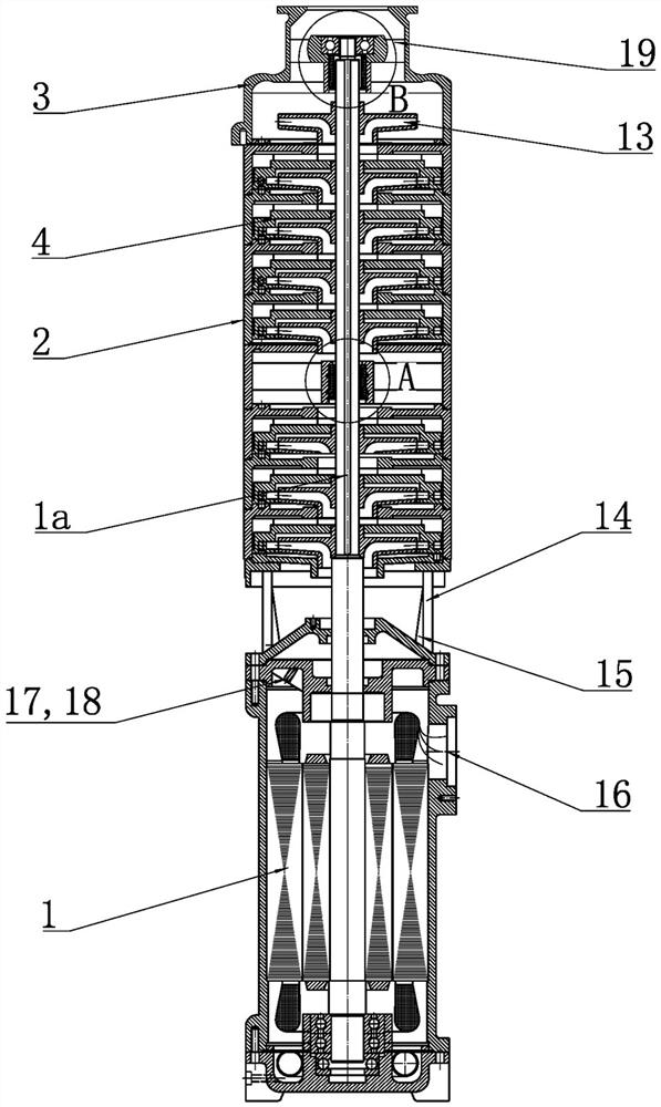
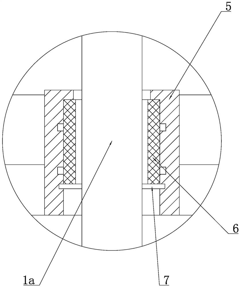
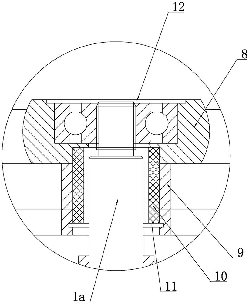
[0019] Such as figure 1 , figure 2 , image 3 As shown, the high-lift multi-stage submersible pump includes a motor part 1 and a pump body 2 installed above the motor part 1. The motor shaft 1a of the motor part 1 extends upward to the top pump cover 3 of the pump body 2 and inside the pump body 2 There are multiple sets of impeller assemblies 4 fixed to the motor shaft 1a. The impeller assemblies 4 include inner impellers and outer guide vanes, which are arranged in parallel upwards in sequence. The upper and lower ends of each guide vane have a stepped structure that can be locked with each other.

[0020] The center of the pump body 2 is provided with a positioning seat 5 with an integrated structure. The positioning...


PUM


Abstract

The invention provides a high-lift multi-stage submersible pump, and belongs to the technical field of fluid machinery. The problem that a motor shaft of an existing multi-stage submersible pump is prone to swinging is solved. The high-lift multi-stage submersible pump comprises a motor part and a pump body mounted above the motor part, a first positioning seat integrated with the pump body is arranged at the center of the middle section in the pump body, a first shaft sleeve is arranged in the first positioning seat, the first shaft sleeve is arranged on a motor shaft in a sleeving mode, andthe top of the first shaft sleeve abuts against the lower end in the first positioning seat and is fixed through a first clamping ring; and a bearing seat and a second positioning seat which are of anintegrated structure are arranged in a pump cover, a second shaft sleeve is arranged in the second positioning seat, the second shaft sleeve is arranged on the motor shaft in a sleeving mode, the twoends of the second shaft sleeve abut against a second clamping ring through the bearing seat, and a bearing used for positioning the end of the motor shaft is arranged in the bearing seat and fixed through a cover plate. According to the high-lift multi-stage submersible pump, a supporting structure is additionally arranged on the motor shaft, and the submersible pump has the advantage of makingthe operation of an impeller assembly more stable.

Description

technical field [0001] The invention belongs to the technical field of fluid machinery, and relates to a submersible pump, in particular to a high lift multistage submersible pump. Background technique [0002] The submersible pump is a water-lifting tool that is directly connected to the motor and the water pump and submerges into the water to work. It has the advantages of simple structure, energy saving, high efficiency, safety and reliability. A multi-stage submersible pump means that there are multiple sets of impeller assemblies connected to the motor shaft of the pump body. Since the impeller assemblies must be arranged axially in sequence, the greater the number, the longer the submersible pump. In the prior art, the motor shaft of the pump body extends to the rear end Generally, there is no supporting structure in the middle or middle part, so it is easy to cause the motor shaft to swing during operation. The longer the pump is, the more obvious the swing is. This p...

Claims


Application Information

Patent Timeline
Patent Type & Authority Applications(China)
IPC IPC(8): F04D1/08F04D13/08F04D29/00F04D29/044F04D29/046F04D29/58
CPCF04D1/08F04D13/08F04D29/007F04D29/044F04D29/046F04D29/5806
Inventor 张显亮
Owner ZHEJIANG YOULI ELECTRIC & MACHINE
Learn More