

Electric rocket device
A rocket and electric technology, applied in defensive devices, offensive equipment, etc., can solve the problems of short interception effective distance, out-of-control aircraft, malicious intrusion, etc., to improve the capture accuracy, improve the moving speed, and avoid misoperation.
- Summary
- Abstract
- Description
- Claims
- Application Information
AI Technical Summary
Problems solved by technology
Method used
Image


Examples
Embodiment Construction
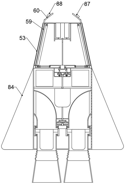
[0030] The present invention is specifically described below in conjunction with accompanying drawing, as Figure 1-12 As shown, an electric rocket device includes a cylindrical casing 1, the lower end of the cylindrical casing 1 is provided with an electric drive mechanism, the upper end of the cylindrical casing 1 is provided with an automatic opening mechanism, and one side of the automatic opening mechanism is provided with a linkage trigger mechanism;
[0031]The electric drive mechanism includes air inlets 2 on both sides of the cylindrical shell 1, an S-shaped air passage 3 is installed on one side of the air inlet 2, a sealed bearing-4 is installed on the lower end of the S-shaped air passage 3, and a sealed bearing-4 is installed on the outer ring of the sealed bearing-4. Rotating ring 5, sealed bearing 2 6 is installed on the lower end side surface of rotating ring 5, straight air channel 7 is installed on the inner ring of sealed bearing 2 6, the lower end of straigh...
PUM
 Abstract
Description
Claims
Application Information