
Latch-hook-type canister-shooting loitering munition missile wing unfolding locking mechanism

A locking mechanism and hook-type technology, which is applied in the direction of projectiles, offensive equipment, weapon types, etc., can solve the problems of static instability and static stability of the whole bomb, spring pins that cannot be inserted into pin holes, spring pins that are easily deformed by force, etc. , to achieve the effect of low matching accuracy, easy to unlock and reuse, and not easy to lose the lock

Pending Publication Date: 2020-11-27
GENERAL ENG RES INST CHINA ACAD OF ENG PHYSICS
View PDF0 Cites 1 Cited by
  • Summary
  • Abstract
  • Description
  • Claims
  • Application Information

AI Technical Summary

Problems solved by technology

If the left and right deployment of the wings is not synchronized, it will cause rapid roll after ejecting from the barrel, and fall to the ground out of control. If the wings cannot be locked reliably after deployment, the aerodynamic shape of the whole bomb will change greatly, resulting in the static instability of the whole bomb. Or the static stability is too high to control the fall to the ground. Therefore, the wing expansion locking mechanism is an important component of the cruise missile, which directly affects the success of the launch of the cruise missile.
[0004] The locking mechanism used in the existing elastic wing deployment locking mechanism has a spring pin. When the spring pin is locked, the matching precision between the spring pin and the pin hole on the elastic wing is high, and there are unreliable locking such as the spring pin cannot be inserted into the pin hole, and the lock is lost after locking. Risk, at the same time, the empty position of the wing after locking is large, and the spring pin is easily deformed by force under the condition of repeated locking, and the spring pin needs to be replaced frequently

Method used


Image

  • Latch-hook-type canister-shooting loitering munition missile wing unfolding locking mechanism
  • Latch-hook-type canister-shooting loitering munition missile wing unfolding locking mechanism
  • Latch-hook-type canister-shooting loitering munition missile wing unfolding locking mechanism

Examples


Embodiment Construction

[0027] The technical solutions in the embodiments of the present invention will be clearly and completely described below in conjunction with the accompanying drawings in the embodiments of the present invention. Obviously, the described embodiments are only a part of the embodiments of the present invention, rather than all the embodiments. Based on the embodiments of the present invention, all other embodiments obtained by those of ordinary skill in the art without creative work shall fall within the protection scope of the present invention.

[0028] The present invention provides the following technical solutions:

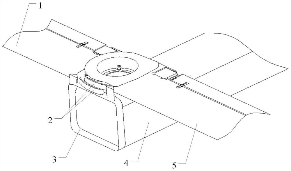
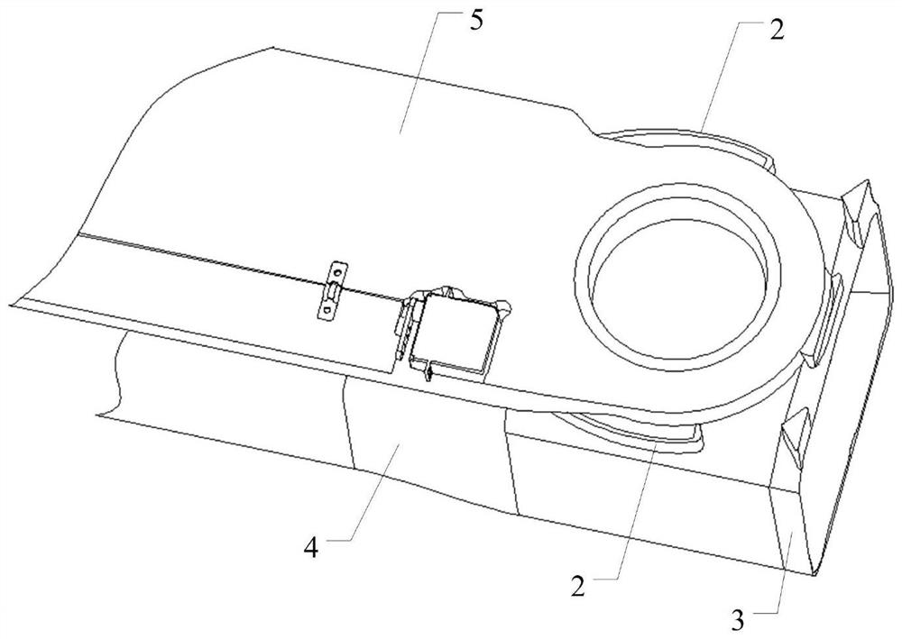
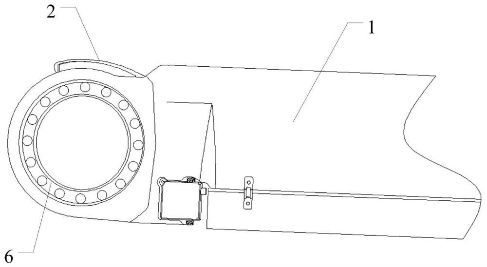
[0029] Such as Figure 1-6 As shown, a lock hook type tube-launched cruise missile wing deployment and locking mechanism, some parts of the cruise missile include a body 4, a first wing 1 and a second wing 5, and the first wing 1 includes a first wing wing Root 6, the second elastic wing 5 includes a second elastic wing wing root 11, and the first elastic wing wing...


PUM


Abstract

The invention discloses a latch-hook-type canister-shooting loitering munition missile wing unfolding locking mechanism. The latch-hook-type canister-shooting loitering munition missile wing unfoldinglocking mechanism comprises two missile locking hooks and a latch hook locking boss, wherein the missile locking hooks are respectively mounted on a first wing root and a second wing root; and the two missile locking hooks are locked and buckled with the latch hook locking boss; and when a first missile wing and a second missile wing are unfolded to the working state, the matching movement process of the missile locking hooks and the latch hook locking boss is not in contact and contact, and the missile locking hooks are deformed after extrusion, and the missile locking hooks are buckled withthe latch hook locking boss. According to the latch-hook-type canister-shooting loitering munition missile wing unfolding locking mechanism, the missile locking hooks are adopted to realize the locking of the missile wings, the structure is simple, the matching precision requirement between all parts in the locking process is low, unlocking is not liable to occurring after locking, and the locking is reliable; and the missile locking hooks are adopted to realize the locking of the missile wings, the unlocking can be completed only by a common screwdriver and other tools during unlocking, theunlocking and reuse are facilitated, the structure is simple, the connection with the missile wings is firm, and the latch hook type canister-shooting loitering munition missile wing unfolding lockingmechanism can be reused multiple times.

Description

Technical field [0001] The invention belongs to the technical field of tube-launched cruise missiles, and specifically relates to a lock hook type tube-launched cruise missile wing deployment and locking mechanism. Background technique [0002] The tube-launched cruise missile is an organic combination of small unmanned aerial vehicle technology and precision guided munition technology. It has the long-term aerial reconnaissance capability of small unmanned aerial vehicles and the precision strike capability of precision guided munitions. It can be used to target out of sight (such as far Distance, reverse slope, obstruction by obstacles, etc.) In the predetermined area, fixed or moving targets that cannot be accurately located in advance can be used for long-time air reconnaissance, and real-time "suicide" attacks can be carried out after the target is found. During daily duties and transportation, each wing surface of the tube-launched cruise missile is folded and loaded in the...

Claims


Application Information

Patent Timeline
Patent Type & Authority Applications(China)
IPC IPC(8): F42B10/14
CPCF42B10/14
Inventor 李永泽卢永刚袁小雅谭晓军李勇钱立新冯高鹏
Owner GENERAL ENG RES INST CHINA ACAD OF ENG PHYSICS
Learn More