
Crack monitoring method and system

A technology for monitoring position and initial position, which is applied in the field of crack monitoring, and can solve problems such as low resolution of crack width change detection, inability to detect or monitor, errors, etc.

Active Publication Date: 2020-11-27
北京思莫特科技有限公司
View PDF4 Cites 2 Cited by
  • Summary
  • Abstract
  • Description
  • Claims
  • Application Information

AI Technical Summary

Problems solved by technology

However, when the optical axis of the camera is not perpendicular to the surface of the structure under test or the surface of the structure under test is not flat, certain errors will be brought about or detection or monitoring cannot be performed at all; The detection resolution of the crack width change that can be achieved by the current public data is also low

Method used


Image

  • Crack monitoring method and system
  • Crack monitoring method and system
  • Crack monitoring method and system

Examples


Embodiment Construction

[0071] The following will clearly and completely describe the technical solutions in the embodiments of the present invention with reference to the accompanying drawings in the embodiments of the present invention. Obviously, the described embodiments are only some, not all, embodiments of the present invention. Based on the embodiments of the present invention, all other embodiments obtained by persons of ordinary skill in the art without making creative efforts belong to the protection scope of the present invention.

[0072] The purpose of the present invention is to provide a crack monitoring method and system, which improves the detection resolution of crack width changes through a high-precision positioning algorithm of digital image correlation (DIC) method, and realizes high-resolution monitoring of crack width changes.

[0073] In order to make the above objects, features and advantages of the present invention more comprehensible, the present invention will be further...


PUM


Abstract

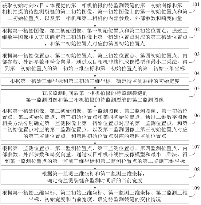
The invention relates to a crack monitoring method and system, and relates to the technical field of crack monitoring. The method comprises the following steps of: determining corresponding initial position points on two initial images by using a three-dimensional DIC method according to the initial images of a to-be-monitored crack shot by two cameras at an initial moment; calculating the initialwidth of the to-be-monitored crack through the initial position point, a binocular camera nonlinear imaging model and an initial three-dimensional coordinate determined by a least square method; determining a corresponding monitoring position point of the initial position point on the monitoring image by utilizing a two-dimensional DIC method according to the monitoring images of the to-be-monitored crack shot by the two cameras after the monitoring time; calculating the current width of the to-be-monitored crack according to the monitoring three-dimensional coordinate determined by the monitoring position point; and according to the initial three-dimensional coordinate, the monitoring three-dimensional coordinate, the initial width and the current width, determining the change conditionof the to-be-monitored crack. According to the invention, the detection resolution of the crack width change is improved through the matching algorithm of the DIC method, and high-resolution monitoring is realized.

Description

technical field [0001] The invention relates to the technical field of crack monitoring, in particular to a crack monitoring method and system. Background technique [0002] At present, the crack detection or monitoring method based on the principle of machine vision basically uses a monocular camera. The implementation process is: firstly, preprocessing and crack recognition are performed on the crack image obtained by the monocular camera to obtain the entire pixel edge of the crack, and then The identified cracks are located on the whole pixel edge for sub-pixel positioning. This enables high-resolution detection or monitoring of fracture width variations. However, when the optical axis of the camera is not perpendicular to the surface of the structure under test or the surface of the structure under test is not flat, certain errors will be brought about or detection or monitoring cannot be performed at all; The detection resolution of the fracture width change that can...

Claims


Application Information

Patent Timeline
Patent Type & Authority Applications(China)
IPC IPC(8): G01C11/00G01C11/02G01B11/00G01B11/14G06F17/15
CPCG01B11/002G01B11/14G01C11/00G01C11/02G06F17/15
Inventor 蔡友发李飞
Owner 北京思莫特科技有限公司
Learn More