
Rotor, motor, compressor, air conditioner and vehicle

A compressor and rotor technology, applied in the field of vehicles, can solve the problems of unreasonable amount and thickness design of permanent magnets, inability to further increase the magnetic load, and reduction of the anti-demagnetization reliability of the motor, so as to improve the anti-demagnetization reliability and reduce the copper loss. , the effect of high power density

Pending Publication Date: 2020-11-27
GUANGDONG WELLING AUTO PARTS CO LTD
View PDF0 Cites 0 Cited by
  • Summary
  • Abstract
  • Description
  • Claims
  • Application Information

AI Technical Summary

Problems solved by technology

[0002] In related technologies, the permanent magnets of the rotor of the variable frequency permanent magnet synchronous motor are arranged in a "one" shape, so that the amount of permanent magnets is limited, and the magnetic load cannot be further increased.
Although the permanent magnet of the motor rotor adopts a "V" or "U" shape to increase the magnetic load, the amount and thickness of the permanent magnet are unreasonable. If the rotor does not have a magnetic assembly, the rotor cannot be saturated and magnetized, resulting in permanent The utilization rate of the magnet is reduced, and the reliability of the anti-demagnetization of the motor is reduced, and there is a risk of demagnetization; if the rotor is assembled with magnetism, it will absorb iron filings, which cannot meet the production requirements of no iron filings and the product requirements of no iron filings inside the compressor

Method used


Image

  • Rotor, motor, compressor, air conditioner and vehicle
  • Rotor, motor, compressor, air conditioner and vehicle
  • Rotor, motor, compressor, air conditioner and vehicle

Examples


Embodiment Construction

[0048] In order to understand the above-mentioned purpose, features and advantages of the present invention more clearly, the present invention will be further described in detail below in conjunction with the accompanying drawings and specific embodiments. It should be noted that, in the case of no conflict, the embodiments of the present application and the features in the embodiments can be combined with each other.

[0049] In the following description, many specific details are set forth in order to fully understand the present invention. However, the present invention can also be implemented in other ways different from those described here. Therefore, the protection scope of the present invention is not limited by the specific details disclosed below. EXAMPLE LIMITATIONS.

[0050] Refer below Figure 2 to Figure 6 The rotor 2, motor and compressor according to some embodiments of the present invention are described.

[0051] Such as figure 2 As shown, a rotor 2 is p...


PUM


Abstract

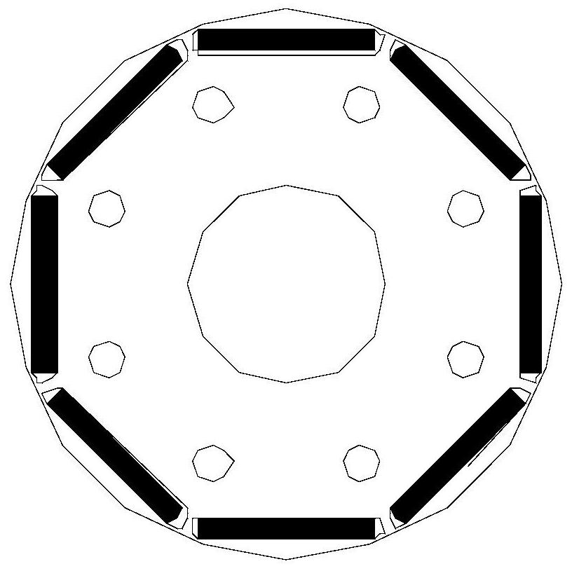
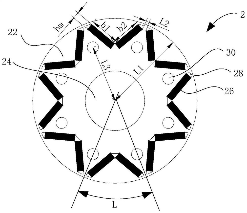
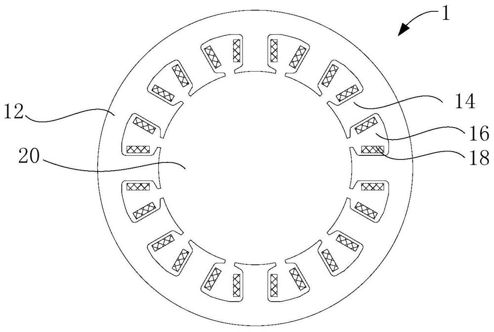
The invention provides a rotor, a motor, a compressor, an air conditioner and a vehicle. The rotor comprises: a rotor core, wherein the rotor core is provided with a plurality of magnet grooves, and the distance from the outer contour line of the rotor core to the geometric center of the rotor core is L1; and permanent magnets arranged in the magnet grooves, wherein the sum of the widths of all the permanent magnets corresponding to a single magnetic pole is bm, the thickness of each permanent magnet in the magnetization direction is hm, the ratio of the length of the outer contour line corresponding to the single magnetic pole to the bm is smaller than or equal to 1.18 and larger than or equal to 1, and the ratio of L1 to hm is less than or equal to 15 and greater than or equal to 10. According to the rotor provided by the invention, the utilization rate of the permanent magnets is improved to the maximum extent, the rotor can be magnetized in a saturated manner and has relatively high demagnetization resistance, and high power density and motor miniaturization of the motor are realized.

Description

technical field [0001] The present invention relates to the technical field of motors, in particular to a rotor, a motor, a compressor, an air conditioner and a vehicle. Background technique [0002] In related technologies, the permanent magnets of the rotor of the variable frequency permanent magnet synchronous motor are arranged in a "one" shape, so that the amount of permanent magnets is limited and the magnetic load cannot be further increased. Although the permanent magnet of the motor rotor adopts a "V" or "U" shape to increase the magnetic load, the amount and thickness of the permanent magnet are unreasonable. If the rotor does not have a magnetic assembly, the rotor cannot be saturated and magnetized, resulting in permanent The utilization rate of the magnet is reduced, and the reliability of the motor against demagnetization is reduced, and there is a risk of demagnetization; if the rotor is assembled with magnetism, it will absorb iron filings, which cannot meet ...

Claims


Application Information

Patent Timeline
Patent Type & Authority Applications(China)
IPC IPC(8): H02K1/27
CPCH02K1/276H02K2213/03
Inventor 郑军洪孙国伟陈汉锡
Owner GUANGDONG WELLING AUTO PARTS CO LTD
Learn More