Infusion apparatus and monitoring device based on infusion apparatus

A monitoring device and infusion set technology, applied in the directions of flow monitors, instruments, flow control, etc., can solve the problems of affecting the infusion process, reducing labor efficiency, patient vascular embolism, etc., to reduce workload, reduce medical accidents, and prevent air pollution. The effect of embolism

Inactive Publication Date: 2020-12-01
WEST CHINA HOSPITAL SICHUAN UNIV
View PDF8 Cites 1 Cited by
  • Summary
  • Abstract
  • Description
  • Claims
  • Application Information

AI Technical Summary

Problems solved by technology

The finger pressure method is to close the regulator, gently squeeze the Mufei dropper with your hand, so that the liquid in the Mufei dropper reaches 1 / 2 to 2 / 3, place the index finger of your left hand under the air section, and wrap the infusion tube tightly around the On the left index finger, winding upwards in sequence until the air bubbles are pressed into the muffi's dropper, the operation is complicated,
[0004] A series of operations such as inverting the dropping funnel or pinching the catheter are required to remove excess gas. If the operation is not done properly, a large amount of liquid and gas will mix and enter the downcomer to form bubble liquid, which will affect the infusion process.
If it is not discovered due to negligence, it may cause harm to the human body or even be fatal. The operation in the process of removing these air bubbles is cumbersome and reduces labor efficiency. If the infusion of the medicine is not detected in time, the air will enter the infusion dropper, which may cause the patient's blood vessel embolism and cause serious medical accidents.

Method used


Image

  • Infusion apparatus and monitoring device based on infusion apparatus
  • Infusion apparatus and monitoring device based on infusion apparatus
  • Infusion apparatus and monitoring device based on infusion apparatus

Examples


Embodiment Construction

[0022] In order to make the purpose, technical solutions and advantages of the present invention clearer, the present invention will be further described in detail below in conjunction with the examples and accompanying drawings. As a limitation of the present invention.

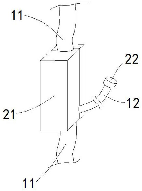
[0023] Such as Figure 1-3 The shown infusion device and the monitoring device based on the infusion device include an infusion device and a monitoring device that cooperate with each other. The infusion device is composed of an infusion hose 11, a drip pot positioned on the infusion hose 11 and a drip pot located on the infusion hose. 11 consists of venous needles and bottle stopper piercers at both ends, and an exhaust pipe 12 is connected to the position where the infusion hose 11 is located from the drip pot to the venous needle;

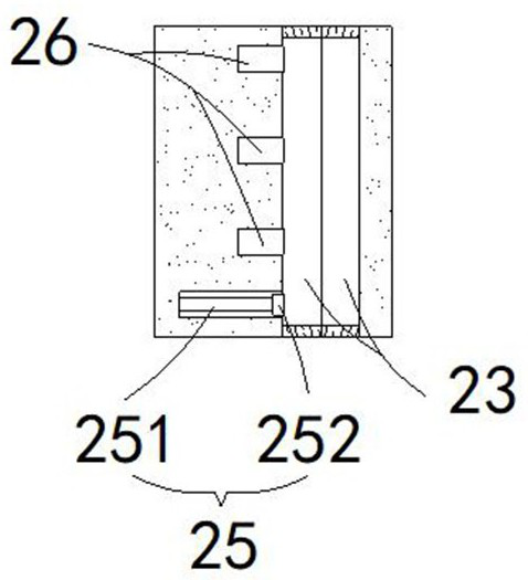
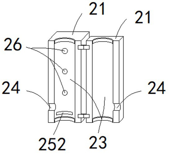
[0024] The monitoring device includes a fixed block 21 and an on-off valve 22 sleeved on the exhaust pipe 13. The fixed block 21 has a fixed hole 23 for the infusion hose 11 ...


PUM


Abstract

The invention discloses an infusion apparatus and a monitoring device based on the infusion apparatus. The infusion apparatus comprises an infusion apparatus body and a monitoring device which are matched with each other, the infusion apparatus body is composed of an infusion hose, a drip cup located on the infusion hose, and an intravenous needle and a bottle stopper puncture device which are arranged at the two ends of the infusion hose, and an exhaust pipe is communicated with the portion, from the drip cup to the intravenous needle, of the infusion hose; and the monitoring device comprisesa fixing block and an opening and closing valve arranged on the exhaust pipe in a sleeving mode, the fixing block is provided with a fixing hole allowing the infusion hose to pass through, and the fixing hole is provided with a limiting hole allowing the exhaust pipe to pass through. The infusion apparatus is simple in structure and high in automation degree, an infusion channel of the infusion hose can be automatically closed after liquid infusion is completed, when air exists in the infusion hose, the air is automatically recognized and exhausted, on one hand, the workload of medical staffis reduced, and on the other hand, the use safety of the infusion device is improved, air embolism is prevented, and medical accidents are reduced.

Description

technical field [0001] The present invention relates to the technical field of medical instruments, and more specifically relates to an infusion set and a monitoring device based on the infusion set. Background technique [0002] At present, clinically used infusion sets are composed of cork piercers, infusion hoses, drip pots, flow regulators, and venous needles. The air bubbles in the hose need to be detected and eliminated in time, otherwise the air bubbles will enter the patient's veins and cause air blockage and endanger life. [0003] There are three commonly used exhaust methods: the upper bomb method, the lower row method and the finger pressure method. The bullet-up method is mainly used for entering a small amount of gas in the infusion set. For a large amount of gas entering in this case, the bullet-up method is very laborious and time-consuming. The lower drainage method needs to be pulled out, and the infusion will be stopped immediately, and the infusion will...

Claims


Application Information

Patent Timeline
IPC IPC(8): A61M5/14A61M5/168A61M5/36
CPCA61M5/14A61M5/365A61M5/16831
Inventor 李霞刘维曾毅
Owner WEST CHINA HOSPITAL SICHUAN UNIV
Why Eureka
Try Eureka