
Tool clamp for machining thin-wall workpiece

A thin-walled workpiece and clamping technology, which is applied in the direction of manufacturing tools, metal processing equipment, metal processing machinery parts, etc., can solve the problems of deformation of thin-walled workpieces and difficult clamping of thin-walled workpieces, and achieve uniform distribution of clamping force Effect

Pending Publication Date: 2020-12-01
CENTRIX EG
View PDF4 Cites 4 Cited by
  • Summary
  • Abstract
  • Description
  • Claims
  • Application Information

AI Technical Summary

Problems solved by technology

[0004] The invention provides a tooling fixture for processing thin-walled workpieces, aiming to solve the problem that the existing tooling fixtures are difficult to clamp thin-walled workpieces and easily cause serious deformation of thin-walled workpieces

Method used


Image

  • Tool clamp for machining thin-wall workpiece
  • Tool clamp for machining thin-wall workpiece
  • Tool clamp for machining thin-wall workpiece

Examples


Embodiment Construction

[0021] The present invention will be further described below in conjunction with the accompanying drawings.

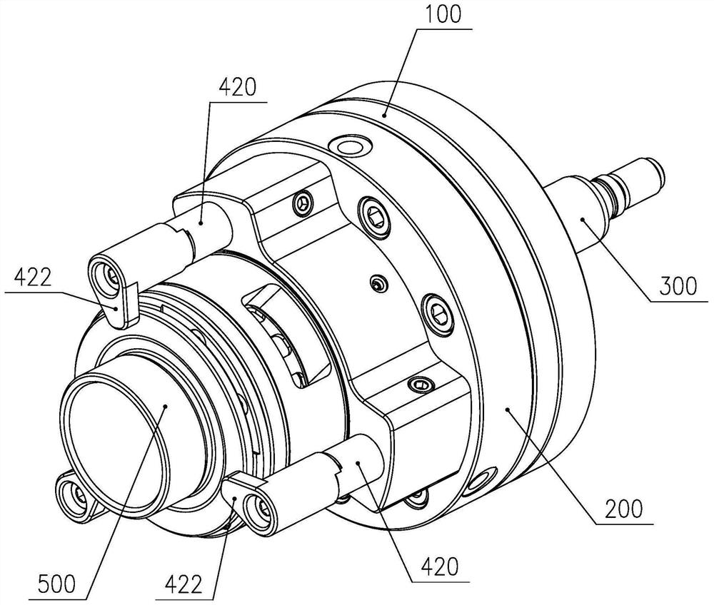
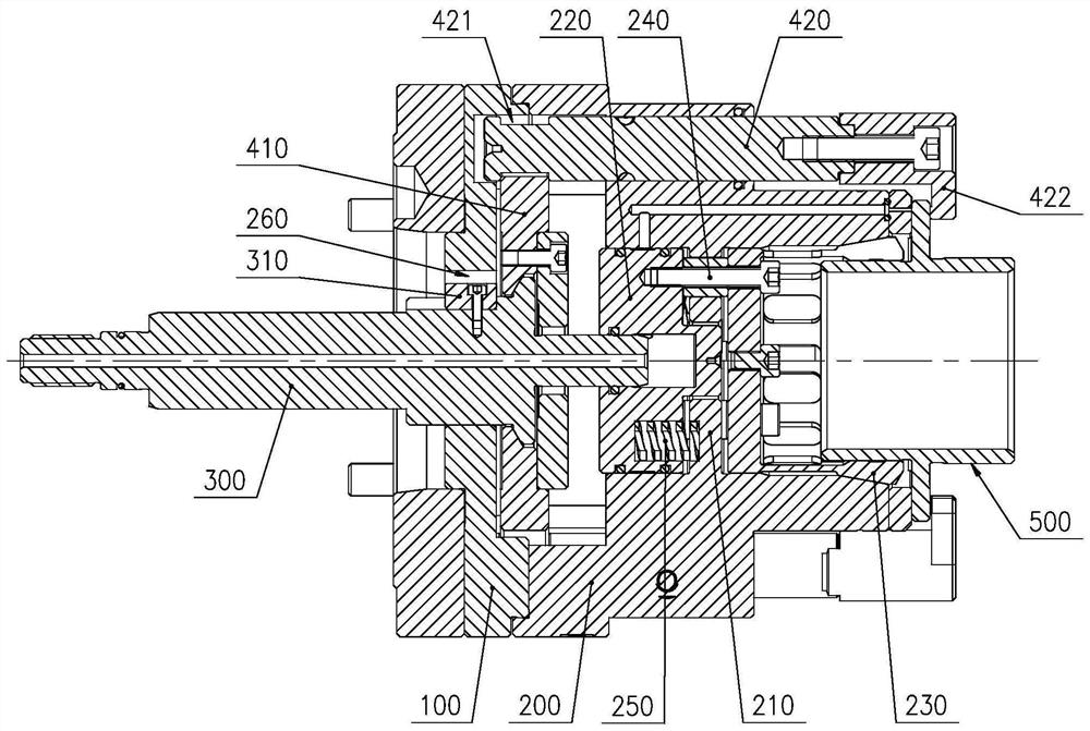
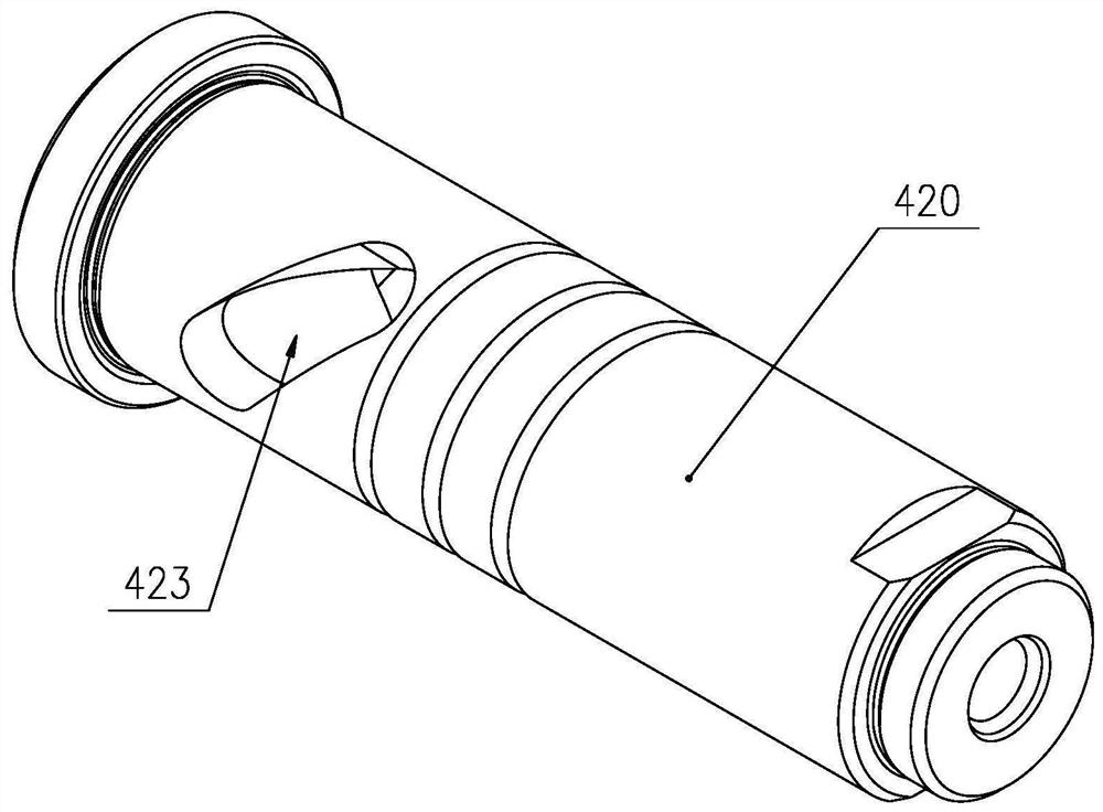
[0022] like figure 2 As shown, the tooling fixture for thin-walled workpiece processing includes a fixture plate 100, a clamping body 200 and a machine tool tie rod 300; A blocking ring 210 is fixed in the clip cavity, and the blocking ring 210 divides the clip cavity into a clip hole and a slider cavity, and a sliding block 220 is slidably arranged in the slider cavity , the clip hole is conical and is provided with a matching elastic jacket 230. The elastic jacket 230 is connected with the sliding block 220 by the connecting piece 240 passing through the stop ring 210. A spring 250 is arranged between the sliding block 220 and the retaining ring 210 ; one end of the machine tool tie rod 300 extends into the working cavity through the fixture plate 100 and corresponds to the sliding block 220 ; the machine tool tie rod 300 can drive the sliding block 220 In the sli...


PUM


Abstract

The invention belongs to the field of clamps, particularly discloses a tool clamp for machining a thin-wall workpiece, and aims to solve the problems that an existing tool clamp difficultly clamps thethin-wall workpiece and serious deformation of the thin-wall workpiece is easily caused. According to the tool clamp for machining the thin-wall workpiece, a sliding block can be driven by a machinetool pull rod to move towards the side away from a clamp disc in a sliding block cavity and compress a spring, then an elastic clamping sleeve moves along with the sliding block, a sleeve opening of the elastic clamping sleeve stretches out of a clamping piece hole, the inner diameter is increased, and the thin-wall workpiece can be conveniently installed; then the machine tool pull rod returns, and the sliding block can be driven to move towards the side close to the clamp disc in the sliding block cavity through the spring in a compressed state; and the elastic clamping sleeve moves along with the sliding block, the sleeve opening of the elastic clamping sleeve retracts into the clamping piece hole, the inner diameter is reduced, the outer wall of the thin-wall workpiece is wrapped and clamped, clamping force is evenly distributed, due to the fact that the elastic force of the spring is fixed, too large clamping force cannot be generated on the thin-wall workpiece, and therefore thethin-wall workpiece cannot deform basically.

Description

technical field [0001] The invention belongs to the field of fixtures, in particular to a tooling fixture for processing thin-walled workpieces. Background technique [0002] The workpiece wall of thin-walled workpieces is very thin, and the radial stiffness is very weak. It is easily deformed by cutting force, cutting heat and clamping force during processing. At the same time, due to the small cross-sectional area of ​​thin-walled workpieces, the external The profile size is relatively large relative to the cross-sectional size. During the machining process, as the rigidity of the workpiece decreases, cutting vibration is prone to occur, which seriously affects the machining quality. Therefore, during the machining process, the clamping of thin-walled workpieces is particularly important. [0003] At present, thin-walled workpieces are generally fixed by fixtures and then mounted on the machine tool for processing. However, due to the above-mentioned characteristics of thi...

Claims


Application Information

Patent Timeline
IPC IPC(8): B23Q3/12
CPCB23Q3/12
Inventor 马洋欧佳林申绍旭赵庆军夏科尧
Owner CENTRIX EG
Learn More