Surface rust removal device for tubular mechanical part machining

A mechanical parts and tubular technology, which is applied in the field of surface rust removal devices for processing tubular mechanical parts, can solve the problems of surface rust of mechanical parts, inability to fix and remove rust of different workpieces, affecting service life, etc., to ensure cleanliness. , Improve the effect of rust removal, the effect of efficient rust removal

Active Publication Date: 2020-12-01
山东蒙阳机械制造有限公司
View PDF5 Cites 4 Cited by
  • Summary
  • Abstract
  • Description
  • Claims
  • Application Information

AI Technical Summary

Problems solved by technology

[0002] Mechanical parts, also known as mechanical components, are the basic components of machinery and are inseparable individual parts that make up machinery and machines. Due to different requirements for use, mechanical parts can be made into different shapes, such as tubular and rectangular Shape, taper, etc., but in the long-term use process, the surface of mechanical parts will be rusted, which will affect its service life
[0003] However, the lengths of the current workpieces are different, so that it is impossible to fix and derust different workpieces, and the current derusting is generally to remove the rust by grinding, and the derusting effect is poor. Finally, the derusting process will Generate more dust and impurities, which will affect the working environment

Method used


Image

  • Surface rust removal device for tubular mechanical part machining
  • Surface rust removal device for tubular mechanical part machining
  • Surface rust removal device for tubular mechanical part machining

Examples


Embodiment Construction

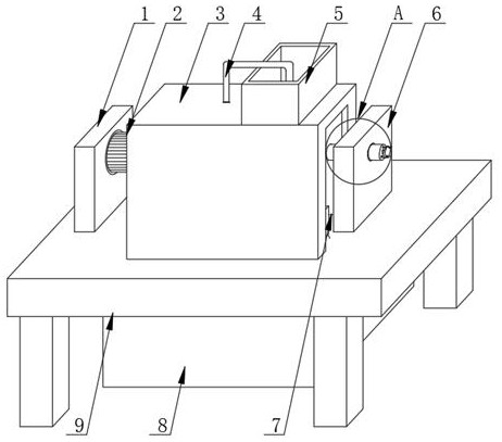
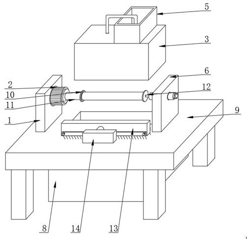
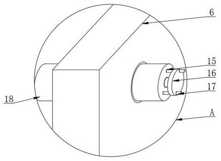
[0027] see Figure 1-7 , in an embodiment of the present invention, a surface derusting device for processing tubular mechanical parts, including a workbench 9, the upper surface of the workbench 9 is respectively equipped with a first fixed plate 1 and a second fixed plate 6 from left to right, The inside of the first fixed plate 1 is equipped with a rotating motor 2, and the driving end of the rotating motor 2 is connected with a rotating shaft 11, and one end of the rotating shaft 11 is fixedly connected with a first limit disc 10, and the inner rotation of the second fixing plate 6 is installed with Rotating column 18, the inside of rotating column 18 is rotated and installed limit rod 16, and the end of limit rod 16 is connected with second limit plate 12, and one side of second limit plate 12 runs through and installs limit column 17, and rotating column One side of 18 is provided with the limit hole 15 that matches mutually with limit post 17, and limit post 17 is cylin...


PUM


Abstract

The invention relates to the technical field of mechanical part surface rust removal, and discloses a surface rust removal device for tubular mechanical part machining. A first fixing plate and a second fixing plate are mounted on the upper surface of a workbench from left to right; a rotating motor is mounted in the first fixed plate; the driving end of the rotating motor is connected with a rotating shaft; one end of the rotating shaft is fixedly connected with a first limiting disc; a rotating column is rotationally mounted in the second fixed plate; and a first electric telescopic rod is mounted on the position, on the front surface of the groove, of the upper surface of the workbench, the telescopic end of the first electric telescopic rod is connected with a moving plate, a protective cover is mounted on the upper surface of the workbench, a rust removal box is fixedly mounted on the upper surface of the protective cover, and a collecting box is arranged on the lower surface of the workbench. Through the effect of the first electric telescopic rod, impurities generated on the workbench can be removed and recycled through the collecting box, and therefore the cleanliness of the workbench is guaranteed.

Description

technical field [0001] The invention relates to the technical field of rust removal on the surface of mechanical parts, in particular to a surface rust removal device for processing tubular mechanical parts. Background technique [0002] Mechanical parts, also known as mechanical components, are the basic components of machinery, and are inseparable individual parts that make up machinery and machines. Due to different use requirements, mechanical parts can be made into different shapes, such as tubular and rectangular Shape, cone, etc., but in the process of long-term use, the surface of mechanical parts will be corroded, which will affect its service life. [0003] However, the lengths of the current workpieces are different, making it impossible to fix and derust different workpieces, and the current derusting is generally to remove the rust by grinding, and the derusting effect is poor. Finally, the derusting process will Generate more dust and impurities, which will af...

Claims


Application Information

Patent Timeline
Patent Type & Authority Applications(China)
IPC IPC(8): B24B27/033B24B41/06B24B47/12B24B47/14B24B41/02B24B55/00B24B55/12C23G3/04B08B1/00B08B13/00
CPCB08B1/002B08B1/008B08B13/00B24B27/033B24B41/02B24B41/062B24B47/12B24B47/14B24B55/00B24B55/12C23G3/04
Inventor 邱海姑
Owner 山东蒙阳机械制造有限公司
Why Eureka
Try Eureka