Gear shifting control method and device
A control method and control device technology, applied in the field of vehicles, can solve the problems of long shift time, poor accuracy, and extensive control, and achieve the effects of reducing synchronization time, improving accuracy, and shortening the power interruption time
- Summary
- Abstract
- Description
- Claims
- Application Information
AI Technical Summary
Problems solved by technology
Method used
Image
Examples
Embodiment 1
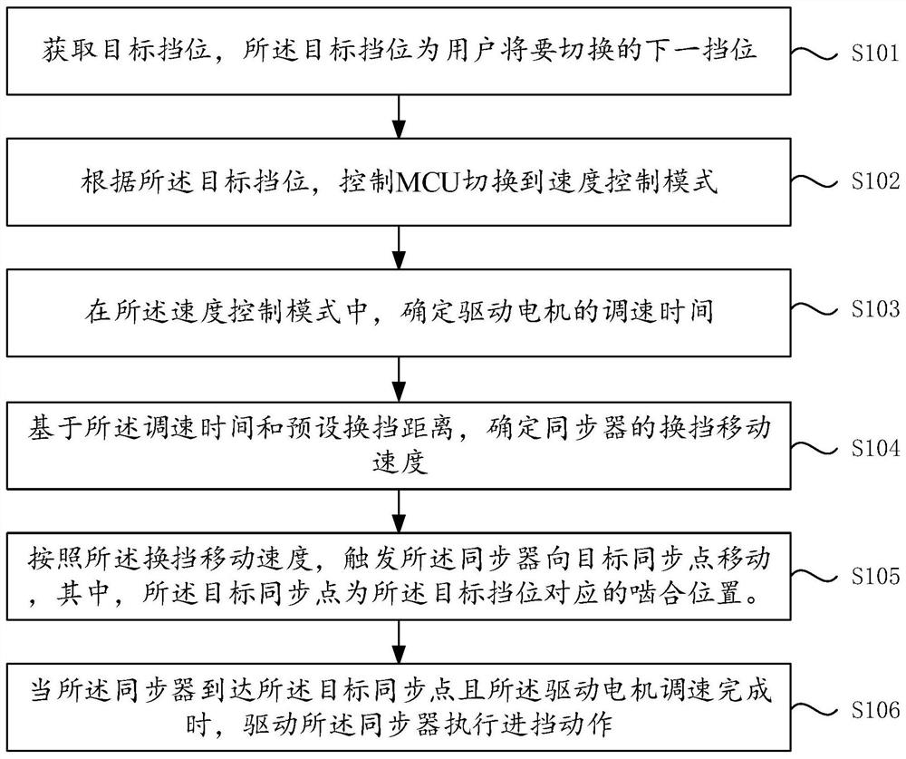
[0060] refer to figure 1 , the present invention provides a shift control method, the method comprising:
[0061] Step S101, acquiring a target gear, which is the next gear to be switched by the user.
[0062]Specifically, the gear shift control method provided by the present invention can be applied to new energy electric vehicles, and the gear shift of the electric vehicle can rely on the gear shift control system of the car, and the gear shift control system can include ACU (Actuation Control Unit, speed reducer control unit), HCU (Hybrid Control Unit, hybrid control unit), MCU (MotorControl Unit, motor control unit), two-speed reducer (including shift motor, shift fork, synchronizer, etc.). HCU is the whole vehicle controller, which decides when to shift gears. ACU can drive gear shift actuators (such as gear shift motors, shift forks, and synchronizers) to complete the gear shift process of the reducer. The MCU can control the drive motor to provide torque or speed to ...
Embodiment 2
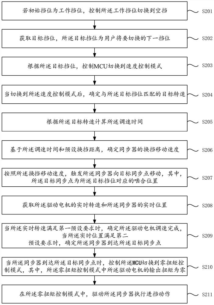
[0077] refer to figure 2 , the present invention provides yet another shift control method, the method comprising:
[0078] Step S201, if the initial gear is the working gear, control the working gear to switch to neutral gear.
[0079] Specifically, similar to the shifting process of traditional fuel vehicles, each shifting process requires the gear lever to be shifted from the neutral position. If the initial gear is not in the neutral position at the beginning of the shift, such as in forward gear, reverse gear, etc., At this time, the gear shift motor can be used to automatically adjust or give the user a prompt to switch the initial working gear to the neutral position, so as to avoid damage to the gear shifting mechanical components.
[0080] Step S202, acquiring a target gear, and the target gear is the next gear to be switched by the user.
[0081] Specifically, the gear shift control method provided by the present invention can be applied to new energy electric veh...
Embodiment 3
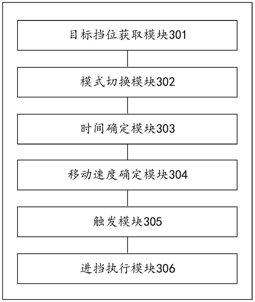
[0105] refer to image 3 , the present invention provides a shift control device, said device comprising:
[0106] The target gear obtaining module 301 is used to obtain the target gear, and the target gear is the next gear to be switched by the user;
[0107] A mode switching module 302, configured to control the MCU to switch to the speed control mode according to the target gear;
[0108] A time determination module 303, configured to determine the speed regulation time of the drive motor in the speed control mode;
[0109] A moving speed determination module 304, configured to determine the shifting moving speed of the synchronizer based on the speed regulation time and the preset shifting distance;
[0110] A trigger module 305, configured to trigger the synchronizer to move to a target synchronization point within the speed regulation time according to the shifting speed, wherein the target synchronization point is the meshing position corresponding to the target gear;...
PUM
 Abstract
Description
Claims
Application Information
 - R&D
- Intellectual Property
- Life Sciences
- Materials
- Tech Scout
- Unparalleled Data Quality
- Higher Quality Content
- 60% Fewer Hallucinations
Browse by: Latest US Patents, China's latest patents, Technical Efficacy Thesaurus, Application Domain, Technology Topic, Popular Technical Reports.
© 2025 PatSnap. All rights reserved.Legal|Privacy policy|Modern Slavery Act Transparency Statement|Sitemap|About US| Contact US: help@patsnap.com


