Dehumidification equipment for power equipment

A technology for power equipment and equipment, applied in lighting and heating equipment, substation/distribution device casings, dry solid materials, etc., to avoid residual moisture

Inactive Publication Date: 2020-12-01
杨晓盼
View PDF0 Cites 4 Cited by
  • Summary
  • Abstract
  • Description
  • Claims
  • Application Information

AI Technical Summary

Problems solved by technology

[0003] Since the water droplets condensed on the condensed aluminum plate on the power box dehumidifier need to condense into a certain mass before they can be discharged downwards, if the humidity inside the power box is not large, the water droplets attached to the condensed aluminum plate will be reduced. When the dehumidifier stops running, the water on the condensation plate will gradually evaporate and follow the air into the power box in reverse, so that the power box dehumidifier will do useless work

Method used


Image

  • Dehumidification equipment for power equipment
  • Dehumidification equipment for power equipment
  • Dehumidification equipment for power equipment

Examples


Embodiment 1

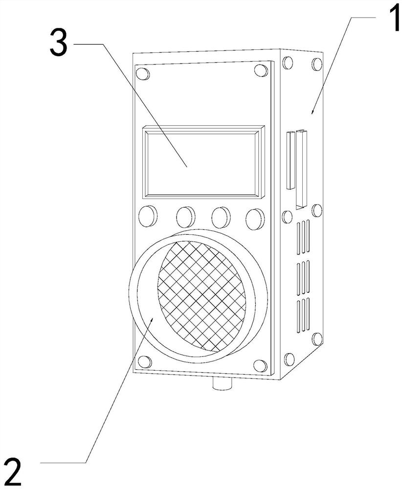
[0026] For example figure 1 -example Figure 5 Shown:

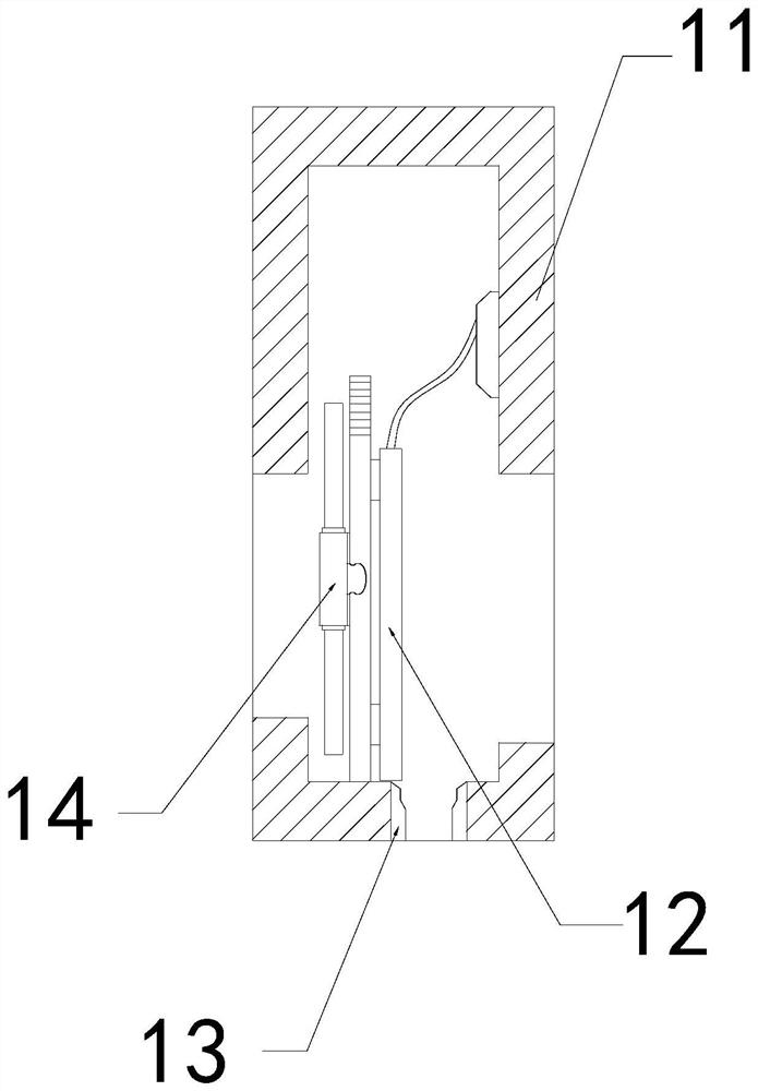
[0027] The invention provides a dehumidification equipment for electric power equipment, the structure of which includes a body 1, an exhaust pipe 2, and a control panel 3. The control panel 3 is embedded and fixed at the front end of the body 1, and the body 1 and the exhaust pipe 2 are integrated. structure; the body 1 includes an outer frame 11, a condensation plate 12, a water outlet 13, and an exhaust fan 14, the condensation plate 12 is installed on the right side of the exhaust fan 14, and the water outlet 13 is integrated with the outer frame 11 structure, the exhaust fan 14 is movably engaged with the outer frame 11.

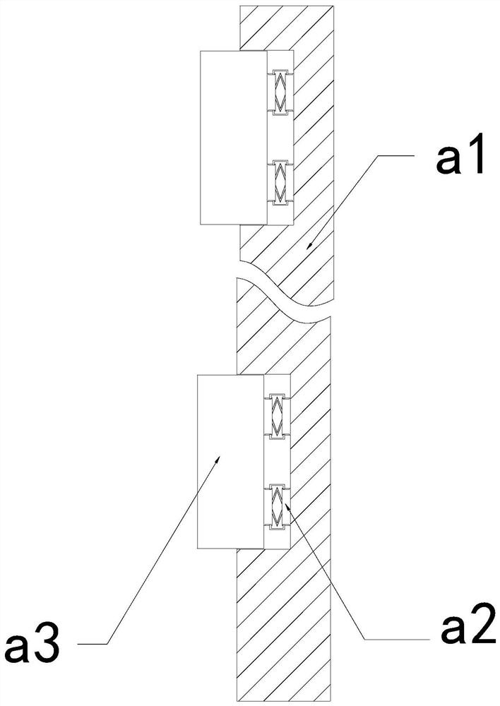
[0028] Wherein, the condensation plate 12 includes a blocking plate a1, an elastic frame a2, and a guide block a3, and the elastic frame a2 is installed between the right side of the inner wall of the blocking plate a1 and the right side of the guide block a3, and the guide block a3 and the right...

Embodiment 2

[0034] For example Figure 6 -example Figure 8 Shown:

[0035] Wherein, the water outlet 13 includes an elastic bar c1, an upper slide plate c2, and a frame c3, the elastic bar c1 is installed between the upper slide plate c2 and the frame body c3, and the inner side of the upper slide plate c2 and the elastic bar c1 is movable. In combination, there are two upper slides c2, which are evenly distributed symmetrically inside the elastic strip c1, and the outward suction is generated by the rotation of the mechanism, which can make the upper slide c2 slide upward along the frame c3, so that the entry The moisture in the frame c3 can be discharged downward along the upper slide plate c2.

[0036] Wherein, the upper sliding plate c2 includes a squeeze roller c21, a deformation surface c22, a receiving plate c23, and a booster block c24. On the right side of the receiving plate c23, the booster block c24 is installed on the left side of the inner wall of the receiving plate c23...


PUM


Abstract

The invention discloses dehumidification equipment for power equipment. The dehumidification equipment structurally comprises a machine body, an exhaust pipe and a control screen, wherein the controlscreen is embedded and fixed at the front end of the machine body, and the machine body and the exhaust pipe are of an integrated structure. According to the invention, water drops on the surface of aplate body can be guided into a guide groove through the plate body, and through pushing force generated to a scraping mechanism through the gathered water drops, the scraping mechanism can rotate, so that the water at the bottom of the guide groove can be scraped into a groove in the bottom of the inner wall of a water removal plate for collection; air is exhausted outwards through the exhaust fan to generate suction force on an upper sliding plate, so that the upper sliding plate slides upwards along an elastic strip; when the exhaust fan stops rotating, the upper sliding plate can be pushed by the elastic strip to slide downwards and descend along a frame body, so that when an extrusion roller slides between two boosting blocks, the deformation surface can be quickly reset, and residual water on the surface of the deformation surface can be bounced off by the deformation surface.

Description

technical field [0001] The invention relates to the field of electric equipment, in particular to a dehumidification equipment for electric equipment. Background technique [0002] The power box dehumidifier is mainly used to dry the air inside the power box. It sucks the air in the power box through the exhaust device, and then resists the sucked air through the condensing aluminum plate, so that the extracted air The moisture in the battery is directly condensed into water droplets on the aluminum plate, and finally the water droplets condense to a certain mass and are discharged from the bottom drain, so as to ensure the dryness of the air inside the power box. Based on the above description, the inventor found that an existing electric power Equipment Dehumidification equipment mainly has the following deficiencies, such as: [0003] Since the water droplets condensed on the condensed aluminum plate on the power box dehumidifier need to condense into a certain mass befo...

Claims


Application Information

Patent Timeline
IPC IPC(8): H02B1/28F26B5/14
CPCF26B5/14H02B1/28
Inventor 杨晓盼
Owner 杨晓盼
Why Eureka
Try Eureka