Ventilation and heat dissipation device of high-low voltage power distribution cabinet

A technology for ventilation and heat dissipation and power distribution cabinets, which is applied in substation/power distribution device shells, cooling/ventilation of substations/switchgears, details of substation/switch layout, etc. Accumulation of dust and other problems, to achieve the effect of easy maintenance, improve maintenance efficiency, and improve work efficiency

Inactive Publication Date: 2020-12-01
杭州墙镪科技有限公司
View PDF0 Cites 7 Cited by
  • Summary
  • Abstract
  • Description
  • Claims
  • Application Information

AI Technical Summary

Problems solved by technology

[0003] However, the ventilation and heat dissipation performance of the head of the ordinary power distribution cabinet is low. The working efficiency of the electrical components in the cabinet is low; some outdoor power distribution cabinets with heat sinks are easy to accumulate dust during operation, and the dust is easy to block the heat sink of the power distribution cabinet. In rainy days, rainwater is easy to enter the power distribution cabinet from the heat sink The interior of the power distribution cabinet cannot provide a dry and ventilated environment for the electrical components inside the power distribution cabinet. The heat dissipation effect of the power distribution cabinet is poor, and the safety of the power distribution cabinet is low.

Method used


Image

  • Ventilation and heat dissipation device of high-low voltage power distribution cabinet
  • Ventilation and heat dissipation device of high-low voltage power distribution cabinet
  • Ventilation and heat dissipation device of high-low voltage power distribution cabinet

Examples


Embodiment Construction

[0030] In order to make the technical means, creative features, goals and effects achieved by the present invention easy to understand, the present invention will be further described below in conjunction with specific embodiments.

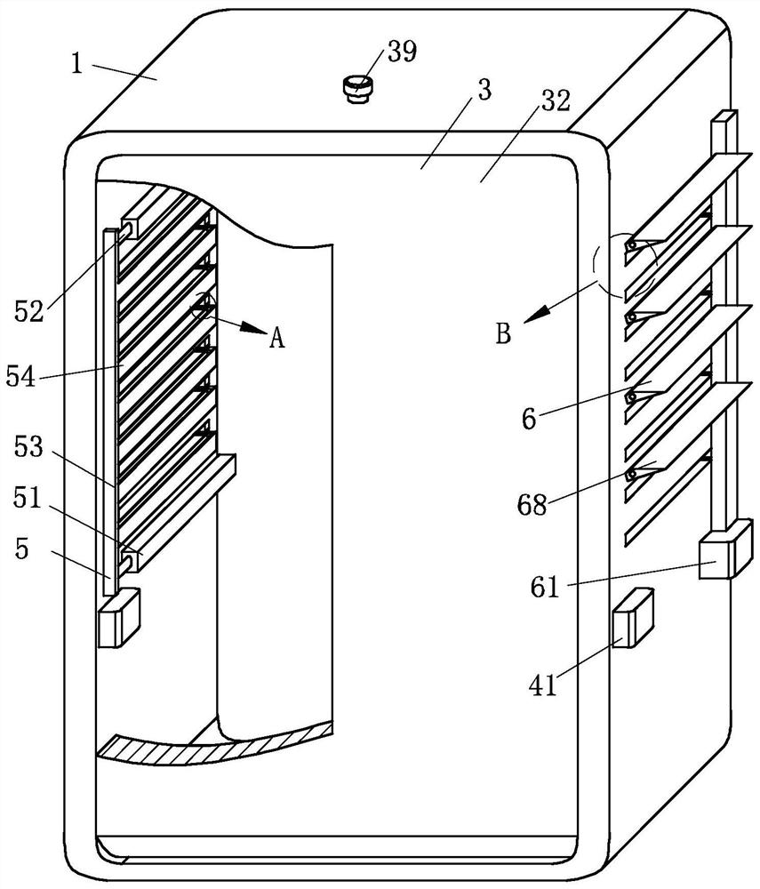
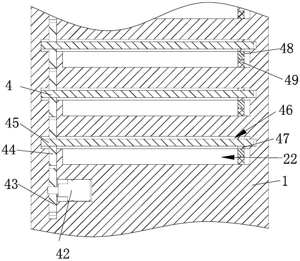
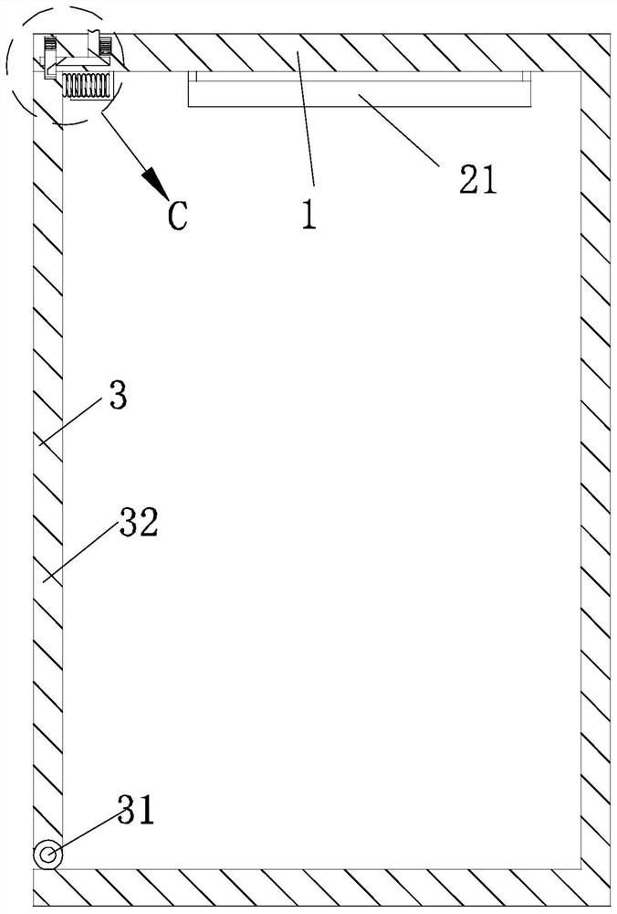
[0031] Such as Figure 1-Figure 11 As shown, the ventilation and heat dissipation device of the high and low voltage power distribution cabinet according to the present invention includes a power distribution cabinet body 1, a heat dissipation structure 2, an engaging structure 3, a cleaning structure 4, a storage structure 5 and a protection structure 6; One end of the heat dissipation structure 2 for dissipating heat from the internal components of the power distribution cabinet body 1 is arranged on the top of the power distribution cabinet body 1, and the other end of the heat dissipation structure 2 is arranged on both sides of the power distribution cabinet body 1 The engaging structure 3 for snapping and closing the power distribution cabin...


PUM


Abstract

The invention belongs to the technical field of power distribution cabinet equipment and relates to a ventilation and heat dissipation device of a high-low voltage power distribution cabinet. The device comprises a power distribution cabinet body, a heat dissipation structure, a clamping structure, a cleaning structure, a storage structure and a protection structure; electrical elements in the power distribution cabinet body are ventilated and cooled through the heat dissipation structure, so that the working efficiency of the electrical elements in the power distribution cabinet body is greatly improved; the power distribution cabinet body is opened or closed through the clamping structure, so that maintenance personnel can conveniently maintain electrical elements in the power distribution cabinet body, and the maintenance efficiency is greatly improved; dust in the heat dissipation structure is cleaned through the cleaning structure, the heat dissipation structure is effectively prevented from being blocked, and the heat dissipation effect of the heat dissipation structure is improved; rainwater or dust can be conveniently stored through the storage structure; rainwater enteringfrom the heat dissipation structure can be conveniently reduced through the protection structure, a dry and ventilated environment is provided for the interior of the power distribution cabinet body,circuit faults are avoided, and the safety of the electrical elements in the power distribution cabinet body is greatly improved.

Description

technical field [0001] The invention relates to the technical field of power distribution cabinet equipment, in particular to a ventilation and heat dissipation device for a high and low voltage power distribution cabinet. Background technique [0002] The power distribution cabinet (box) is divided into power distribution cabinet (box), lighting distribution cabinet (box), metering cabinet (box), and is the final equipment of the power distribution system. The power distribution cabinet is the general name of the motor control center; the power distribution cabinet is used in the occasions where the load is relatively scattered and there are few circuits; the motor control center is used in the occasions where the load is concentrated and there are many circuits; The electric energy is distributed to the nearest loads. This level of equipment shall provide protection, monitoring and control of the load. [0003] However, the ventilation and heat dissipation performance of...

Claims


Application Information

Patent Timeline
Patent Type & Authority Applications(China)
IPC IPC(8): H02B1/56H02B1/30H02B1/32H02B1/28B08B1/00
CPCB08B1/002H02B1/28H02B1/30H02B1/32H02B1/565
Inventor 陈梓健
Owner 杭州墙镪科技有限公司
Why Eureka
Try Eureka