

Rotor structure of disc type motor
A technology of rotor structure and disc motor, applied in the direction of magnetic circuit shape/style/structure, electrical components, electromechanical devices, etc., can solve the problems of reduced motor performance, reduced adhesive strength, hidden safety hazards, etc., to improve the fixing effect and enhance Fixed effect, effect to prevent displacement
- Summary
- Abstract
- Description
- Claims
- Application Information
AI Technical Summary
Problems solved by technology
Method used
Image

Examples
no. 1 example
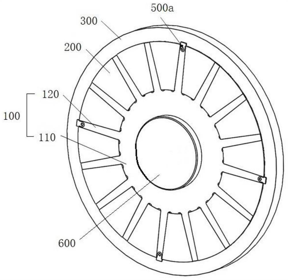
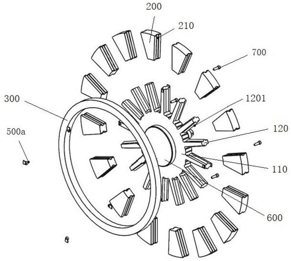
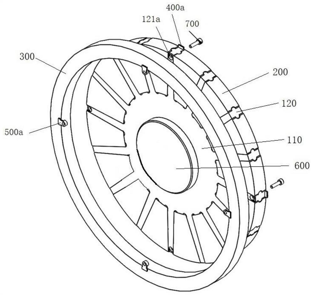
[0047] like Figure 1 to Figure 7 As shown, the first stopper 400 a is integrally formed with the support part 120 , and the second stopper 500 a is detachably connected to the support part 120 .
[0048] Specifically, refer to Figure 7 , the second stopper 500a includes a connecting portion 510a and an abutting portion 520a, the connecting portion 510a is connected to the abutting portion 520a, the connecting portion 510a is installed on the support portion 120, the The abutting portion 520 abuts against a side of the hoop 300 away from the first stopper 400a.
[0049] The connecting part 510a can be sleeved on the supporting part 120, making the assembly of the two more convenient and quick, refer to image 3 and Figure 4 , the side of the supporting part 120 facing away from the first stopper 400a is provided with a first set hole 121a, when the connecting part 510a is sleeved in the first set hole 121a, the abutting part 520a Abutting against a side of the hoop 300 a...
no. 2 example
[0061] like Figure 8 to Figure 12 As shown, the difference from the first embodiment is that both the first stopper 400 b and the second stopper 500 b are integrally formed with the support part 120 .
[0062] like Figure 10 and Figure 11 As shown, the number of the first stopper 400b and the second stopper 500b are consistent, and they are arranged on the same support portion 120 in one-to-one correspondence. Of course, the first stopper 400b and the second stopper 500b may be disposed on different support portions 120 . For example, in two adjacent support parts 120 , one of the support parts 120 is provided with a first stopper 400 b, and the other support part 120 is provided with a second stopper 500 b.
[0063] Preferably, a plurality of first stoppers 400b and second stoppers 500b are arranged equidistantly along the outer periphery of the base 110 .
[0064] The hoop 300 can be made of fiber material, and the fiber includes glass fiber or carbon fiber, and is fi...
no. 3 example
[0069] like Figure 13 to Figure 17 As shown, the difference from the first embodiment is that both the first stopper 400c and the second stopper 500c are detachably connected to the support part 120 .
[0070] The first stopper 400c may be fixed on the support part 120 by a fastener, and the head of the fastener is embedded in a side of the support part 120 away from the first stopper 400c. refer to Figure 16 The support part 120 is provided with the installation hole 121c through which the fastener passes, and the fastener passes through the installation hole 121c and is screwed to the first stopper 400c. The second stopper 500c can also be fixed on the support part 120 by a fastener, and the head of the fastener fixing the second stopper 500c is embedded in the support part 120 away from the first One side of the second stopper 500c.
[0071] like Figure 16 and Figure 17As shown, the support part 120 is provided with a second card slot 122c, and the second stopper 5...
PUM
 Abstract
Description
Claims
Application Information