Plate-type fractionating tower

A fractionation tower and plate-type technology, applied in the field of plate-type fractionation towers, can solve the problems of reducing gas back-mixing, reducing liquid load, and not being able to fit completely, so as to achieve the effect of improving the fractionation effect

Inactive Publication Date: 2020-12-04
朱文艳
View PDF6 Cites 0 Cited by
  • Summary
  • Abstract
  • Description
  • Claims
  • Application Information

AI Technical Summary

Problems solved by technology

[0003] In the Chinese invention patent (application number: 2019113305316), the present invention discloses a plate fractionation tower, including a tower body, the top of the tower body is fastened with an upper head, and the inner upper end of the tower body is fixedly connected with a Demister, the inside of the tower body is provided with a sieve plate, the front and rear ends of the sieve plate are sleeved with clips, and are clipped with the inner wall of the tower body through the clips, the left side of the sieve plate A liquid receiving pan is provided, and a downcomer is provided on the right side of the sieve plate; a plate type fractionation tower according to the present invention can effectively remove the liquid foam entrained by the gas by adding a demister to reduce gas back-mixing, It can effectively reduce the height of the foam layer in the downcomer and reduce the liquid load of the downcomer. It can not only recover the effective components, but also create favorable conditions for the downstream process of the gas, and the protective net set in the demister can protect the The wire mesh is protected to prevent the wire mesh from being scratched during transportation, installation or work, so that the wire mesh is deformed and affects the demister efficiency of the demister; Part of it is controlled by the valve. Since the main component of the valve is the valve plate, and the valve plate is mostly made of metal. During the long-term control of the liquid, the valve plate is easy to rust, which will cause the valve to be stuck in use. At the same time, due to the rust of the valve plate in the valve, it cannot be completely fitted, and the liquid drips from top to bottom without artificial control, which affects the fractionation of the liquid by the hot steam, resulting in poor fractionation of the liquid, making the The technical solution is limited

Method used


Image

  • Plate-type fractionating tower
  • Plate-type fractionating tower
  • Plate-type fractionating tower

Examples


specific Embodiment approach

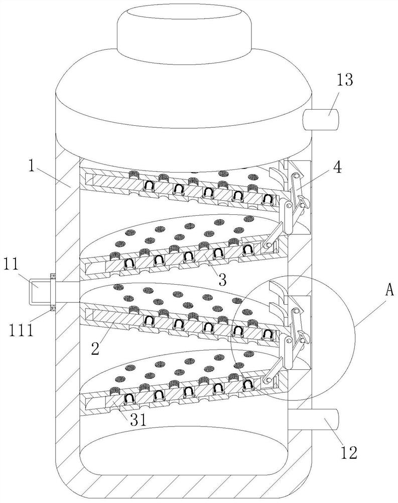
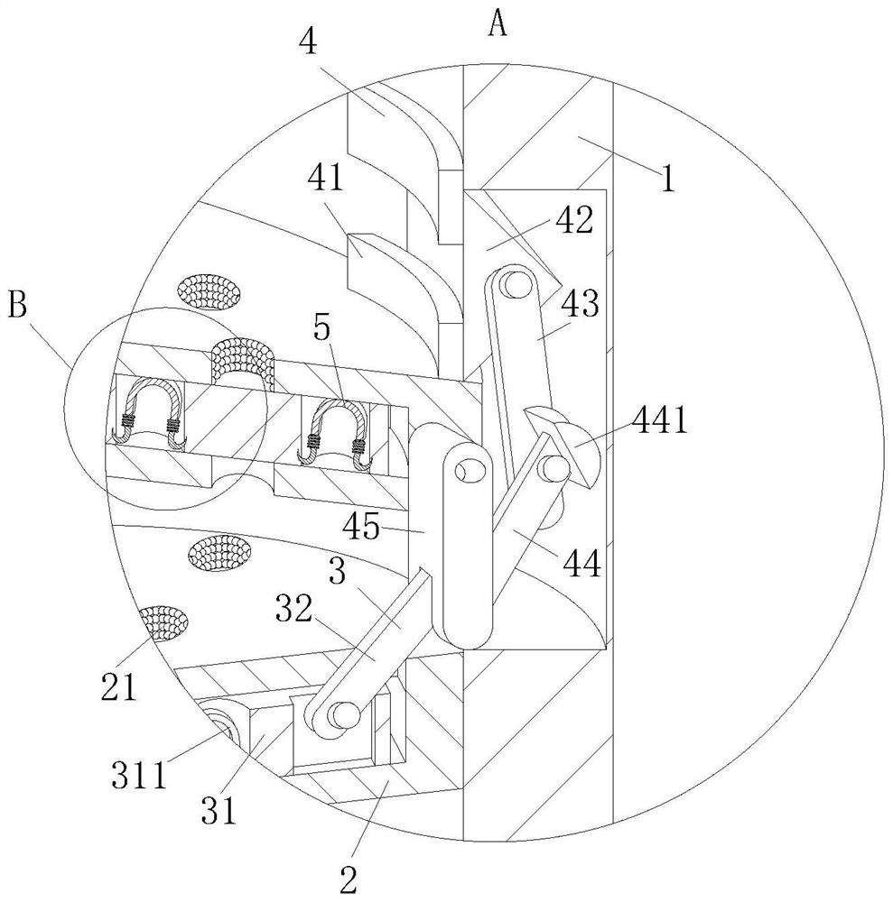
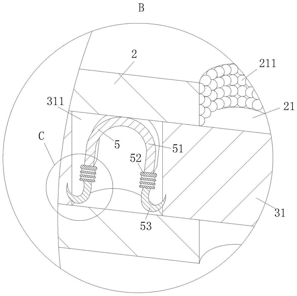
[0028] As a specific embodiment of the present invention, the control unit 3 includes a No. 2 plate 31 and a No. 3 rod 32; a group of No. 2 holes 311 are evenly arranged on the No. 2 plate 31, and the No. 2 plate 31 is placed in the groove In the channel, in the initial state, there is no communication between the No. 2 hole 311 and the No. 1 hole 21; one end of the No. 3 rod 32 is rotated and installed on the No. 1 plate 45, and the other end is hinged with the No. 2 plate 31, and each tray 2 There is an avoidance groove corresponding to the movement of No. 3 rod 32 on the top, through the mutual cooperation between No. 1 plate 45 and No. 3 rod 32, the communication between No. 1 hole 21 and No. 2 hole 311 is realized; when No. 1 plate 45 moves away from When one side of the groove moves, the No. 1 plate 45 pushes the No. 3 rod 32, so that the No. 2 plate 31 moves in the channel, and then realizes the communication between the No. 1 hole 21 and the No. 2 hole 311, so that two ...


PUM


Abstract

The invention belongs to the technical field of chemical engineering, and particularly relates to a plate-type fractionating tower which comprises a tower body and a group of tower plates, one group of tower plates is located in the tower body, each tower plate is obliquely arranged and connected to the inner wall of the tower body, a channel is formed in each tower plate, a control unit is arranged in each channel, a groove is formed in the tower body located at the lowest end of each tower plate, and an adjusting unit is arranged in each groove; each adjusting unit comprises a group of barrier plates, a wedge block, a first rod, a second rod and a first plate; by arranging the adjusting units, a wedge-shaped block is extruded by liquid, and the first rod and the second rod are matched with each other, so that the first plate swings, the liquid flows from top to bottom, the defect that a valve is traditionally used for controlling is overcome, the liquid is subjected to orderly fractionation operation, and the fractionation effect of the liquid is improved.

Description

technical field [0001] The invention belongs to the technical field of chemical industry, in particular to a plate type fractionation tower. Background technique [0002] Fractional distillation is a common method for separating liquid mixtures by using the differences in boiling points of liquid mixtures. This method is widely used in petroleum refining to separate various oil products. The plate fractionation tower is a common separation device in petrochemical enterprises, including the fractionation tower cylinder and the staggered trays in the cylinder. [0003] In the Chinese invention patent (application number: 2019113305316), the present invention discloses a plate fractionation tower, including a tower body, the top of the tower body is fastened with an upper head, and the inner upper end of the tower body is fixedly connected with a Demister, the inside of the tower body is provided with a sieve plate, the front and rear ends of the sieve plate are sleeved with c...

Claims


Application Information

Patent Timeline
Patent Type & Authority Applications(China)
IPC IPC(8): B01D3/22
CPCB01D3/22
Inventor 朱文艳钱露露
Owner 朱文艳
Why Eureka
Try Eureka