Building sewage treatment device and method

A technology for sewage treatment devices and buildings, which is applied in the directions of centrifugal separation of water/sewage treatment, separation methods, filtration treatment, etc. Effect

Inactive Publication Date: 2020-12-04
刘雪莲
View PDF1 Cites 3 Cited by
  • Summary
  • Abstract
  • Description
  • Claims
  • Application Information

AI Technical Summary

Problems solved by technology

[0002] A construction site is a place where construction projects are being developed and civil engineering is being carried out. Its scope is often closed by hoardings, barbed wire or walls to restrict the entry and exit of personnel, materials, machinery and vehicles. A large amount of sewage will be generated on the construction site. Such Sewage often contains a lot of sediment and concrete, and the treatment efficiency for construction sewage is low
[0003] Chinese Utility Model Patent Publication No. CN208762261U proposes a construction wastewater treatment device, which improves the treatment efficiency of the construction wastewater treatment device, prevents the residues in the through holes from accumulating for a long time to cause blockage, facilitates the cleaning of the filter screen, and effectively treats the waste water. The treatment and filtration improves the practicability of the construction wastewater treatment device, but it is inconvenient to clean the solid residues such as sediment in the conical cylinder, which may easily lead to clogging of the slag discharge pipe, and sediment, concrete, etc. stick to the inner wall of the conical cylinder If it is not cleaned for a long time, the actual volume of the conical cylinder will be reduced, and the capacity of a single treatment of sewage will be lower, which will reduce the efficiency of sewage treatment.

Method used


Image

  • Building sewage treatment device and method
  • Building sewage treatment device and method
  • Building sewage treatment device and method

Examples


Embodiment Construction

[0030] In order to make the object, technical solution and advantages of the present invention clearer, the present invention will be further described in detail below in combination with specific embodiments and with reference to the accompanying drawings. It should be understood that these descriptions are exemplary only, and are not intended to limit the scope of the present invention. Also, in the following description, descriptions of well-known structures and techniques are omitted to avoid unnecessarily obscuring the concept of the present invention.

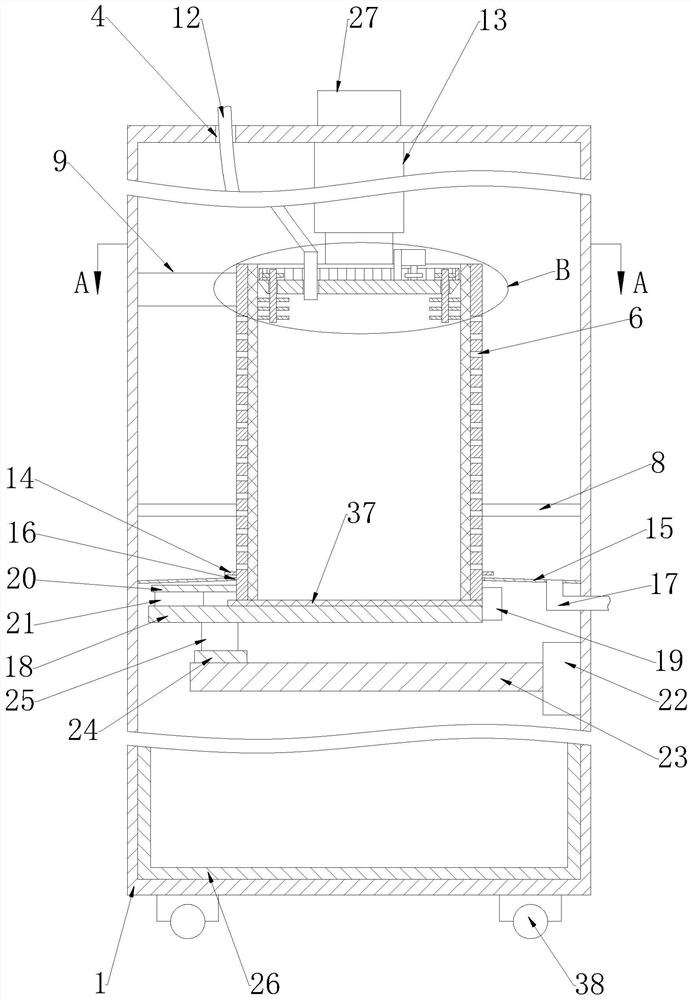
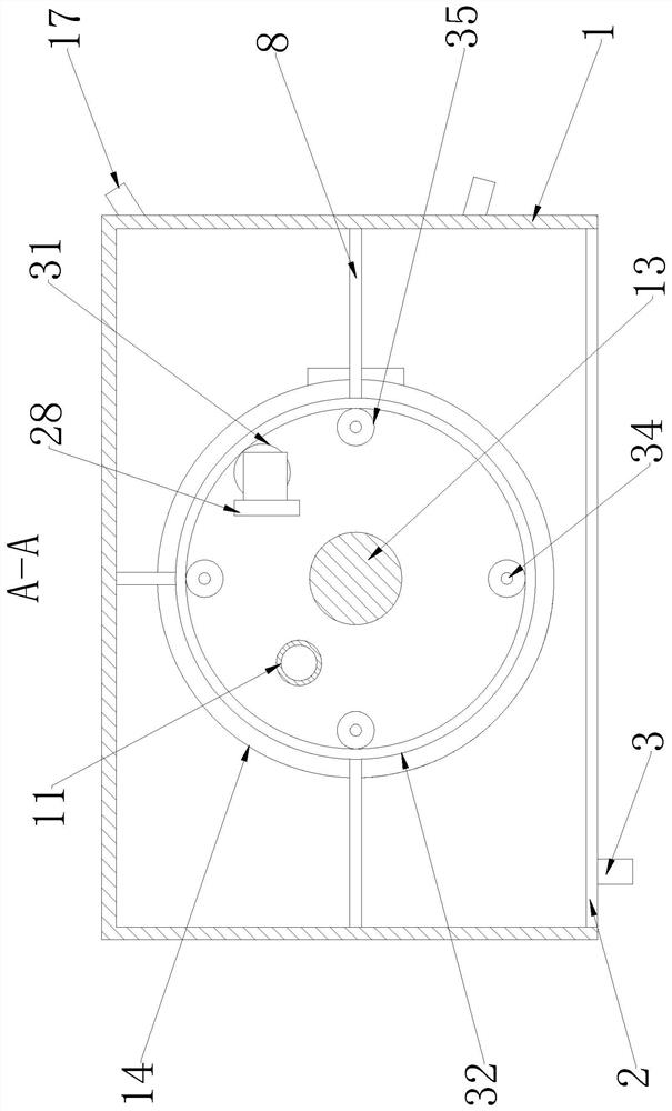
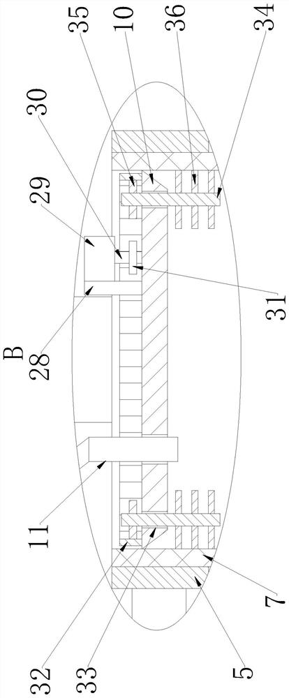
[0031] Such as Figure 1-4 As shown, a building sewage treatment device and method proposed by the present invention include a box body 1, a cylinder body 5, a lifting plate 10, a sewage hose 12, an electric telescopic rod 13, a ring 14, a deflector plate 15, and a water outlet pipe. 17. Bottom sealing plate 18, second support plate 20, third support plate 23, sludge box 26 and controller 27;

[0032]A sewage discharge ...


PUM


Abstract

The invention discloses a building sewage treatment device and method. The device comprises a box body, a cylinder body, a lifting plate, an electric telescopic rod, a circular ring, a flow guide plate, a water outlet pipe, a bottom sealing plate, a second supporting plate, a third supporting plate and a controller, wherein multiple groups of supporting rods are arranged on the inner wall of the box body; a sludge box is arranged at the inner side of the bottom of the box body; the outer wall of the cylinder body is rotationally connected with the end parts of the multiple groups of supportingrods; the electric telescopic rod is arranged at the inner side of the top of the box body; the lifting plate is arranged at the bottom of the electric telescopic rod; the circular ring is horizontally arranged on the outer wall of the cylinder body; the flow guide plate is arranged on the inner wall of the box body; the water outlet pipe is arranged on the flow guide plate; the bottom sealing plate is a metal plate; the second supporting plate is arranged on the outer wall of the bottom of the cylinder body; a permanent magnet is arranged at the bottom of the second supporting plate; a second rotating mechanism is arranged on the inner wall of the box body; an electromagnet is arranged on a sliding block; and the controller is arranged on the outer side of the top of the box body. According to the device, water can be quickly separated from solid substances such as silt and concrete, and the solid substances such as the silt and the concrete in the cylinder body fall into the sludgebox in time.

Description

technical field [0001] The invention relates to the technical field of sewage treatment, in particular to a building sewage treatment device and method. Background technique [0002] A construction site is a place where construction projects are being developed and civil engineering is being carried out. Its scope is often closed by hoardings, barbed wire or walls to restrict the entry and exit of personnel, materials, machinery and vehicles. A large amount of sewage will be generated on the construction site. Such Sewage often contains a large amount of sediment and concrete, and the treatment efficiency for construction sewage is low. [0003] Chinese Utility Model Patent Publication No. CN208762261U proposes a construction wastewater treatment device, which improves the treatment efficiency of the construction wastewater treatment device, prevents the residues in the through holes from accumulating for a long time to cause blockage, facilitates the cleaning of the filter ...

Claims


Application Information

Patent Timeline
Patent Type & Authority Applications(China)
IPC IPC(8): B01D33/11B01D33/46C02F1/38
CPCB01D33/11B01D33/466C02F1/001C02F1/38
Inventor 刘雪莲
Owner 刘雪莲
Why Eureka
Try Eureka