Solid-liquid separation device applied to sewage treatment system

A sewage treatment system and solid-liquid separation technology, applied in the direction of filtration separation, separation methods, chemical instruments and methods, etc., can solve the problems of the efficiency of sewage solid-liquid separation, etc., to facilitate solid-liquid separation, increase impact force, The effect of preventing shedding

Inactive Publication Date: 2020-12-04
刘海容
View PDF4 Cites 1 Cited by
  • Summary
  • Abstract
  • Description
  • Claims
  • Application Information

AI Technical Summary

Problems solved by technology

A solid-liquid separation device for primary sewage treatment in the above-mentioned patent has the following disadvantages: when the existing device separates sewage from solid-liquid, part of the sewage will be submerged in the solid waste. Therefore, when separating solid-liquid When the sewage is submerged in the solid waste, it may affect the efficiency of solid-liquid separation of sewage

Method used


Image

  • Solid-liquid separation device applied to sewage treatment system
  • Solid-liquid separation device applied to sewage treatment system
  • Solid-liquid separation device applied to sewage treatment system

Examples


Embodiment 1

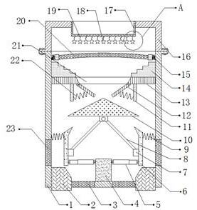
[0030] refer to Figure 1-3 , a solid-liquid separation device applied to a sewage treatment system, comprising a box body 1, both sides of the outer wall of the bottom of the box body 1 are provided with drainage outlets, and the inner walls of the two drainage outlets are connected with a first filter screen 3 by bolts , the outer walls on both sides of the box body 1 are provided with a plurality of filter holes 23, the top outer wall of the box body 1 is connected with a box cover 16 by bolts, and the top outer wall of the box cover 16 is provided with a water inlet, and the inner wall of the water inlet is connected by bolts A filter bucket 17 is connected, and the bottom inner wall of the box body 1 is connected with a fixed block 4 by bolts, and the outer walls on both sides of the fixed block 4 are connected with telescopic rods 5 by hinges, and the outer walls of one side of the two telescopic rods 5 are connected by hinges. An extruded plate 6 is connected, and a fix...

Embodiment 2

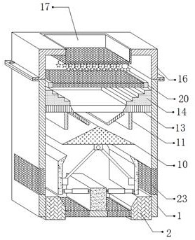
[0039] refer to Figure 4-5 , a solid-liquid separation device applied to a sewage treatment system. Compared with Embodiment 1, this embodiment has two rotating shafts 24 connected by bearings between the inner walls of the opposite sides of the box body 1, and the two rotating shafts 24 Located between the support plate 13 and the second filter screen 20 , blades 25 are connected to the outer walls of the two rotating shafts 24 by bolts, and the outer walls of the blades 25 are provided with a plurality of barbs 26 .

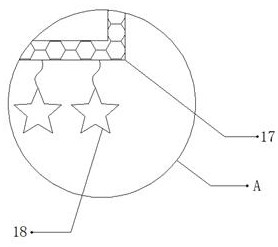
[0040] Working principle: when in use, the sewage that needs solid-liquid separation is filled into the interior of the box 1 through the filter bucket 17, and the sewage is initially treated through the filter bucket 17, and the impurities mixed in the sewage can be suspended on the pendant through the pendant 18 18, in order to carry out solid-liquid separation to sewage, the shape of pendant 18 is star shape, can effectively hang solid waste, prevents that ...


PUM


Abstract

The invention discloses a solid-liquid separation device applied to the sewage treatment system. The device comprises a box body, water outlets are formed in the two sides of the outer wall of the bottom of the box body, first filter screens are fixedly connected to the inner walls of the two water outlets, a plurality of filter holes are formed in the outer walls of the two sides of the box body,a box cover is fixedly connected to the outer wall of the top of the box body, a water inlet is formed in the outer wall of the top of the box cover, a filter cone is fixedly connected to the inner wall of the water inlet, a fixing block is fixedly connected to the inner wall of the bottom of the box body, telescopic rods are connected to the outer walls of the two sides of the fixing block through hinges, and extrusion plates are connected to the outer walls of one sides of the two telescopic rods through hinges. According to the device, solid waste can be subjected to extrusion treatment, the situation that the device cannot effectively conduct solid-liquid separation on the sewage due to the fact that the impact strength of the sewage is weak can be prevented, the solid waste doped inthe sewage can be retained on the second guide plate, and the situation that the solid waste falls off from the hanging piece due to water flow can be prevented.

Description

technical field [0001] The invention relates to the technical field of sewage treatment, in particular to a solid-liquid separation device applied to a sewage treatment system. Background technique [0002] At present, in terms of sewage treatment, it is divided into three stages of treatment, of which the stage one includes solid-liquid separation, and its main function is to separate the larger solids contained in the liquid. [0003] After retrieval, the Chinese patent authorization number is CN107935108B, which discloses a solid-liquid separation device for primary sewage treatment, including a bottom hollow shell and a top hollow shell. The bottom of the bottom hollow shell is equipped with a plurality of connecting plates through bolts, each A support rod is installed at the center of the bottom of each connecting plate. The present invention utilizes the principle of centrifugal force to realize the filtering effect, and the device can freely assemble and disassemble...

Claims


Application Information

Patent Timeline
Patent Type & Authority Applications(China)
IPC IPC(8): B01D36/00
CPCB01D36/00
Inventor 刘海容
Owner 刘海容
Why Eureka
Try Eureka