Driving device of degree-of-freedom printing base table for 3D printing equipment

A 3D printing and driving device technology, applied in the direction of additive processing, etc., can solve the problems of unqualified processed products, unable to meet the printing requirements of cylindrical printing abutments, and difficult to meet the requirements of axial symmetry for rotating parts, so as to ensure quality, The effect of simple structure and convenient use

Pending Publication Date: 2020-12-04
ZHEJIANG YIDONG TECH CO LTD
View PDF1 Cites 2 Cited by
  • Summary
  • Abstract
  • Description
  • Claims
  • Application Information

AI Technical Summary

Problems solved by technology

[0006] 1. Generally, it can only move up and down and print layer by layer. For some rotating parts, it is difficult to meet the requirements of axisymmetric during processing, resulting in unqualified processed products;
[0007] 2. It is unable to play a good supporting role and drive its rotation and up-and-down movement for larger long-axis 3D printing equipment with degrees of freedom to print abutments (multiple parts can be printed on a single printing abutment);
[0008] 3. It is only suitable for platform-type printing abutments, and cannot meet the printing requirements of some cylindrical printing abutments

Method used


Image

  • Driving device of degree-of-freedom printing base table for 3D printing equipment
  • Driving device of degree-of-freedom printing base table for 3D printing equipment
  • Driving device of degree-of-freedom printing base table for 3D printing equipment

Examples


Embodiment 1

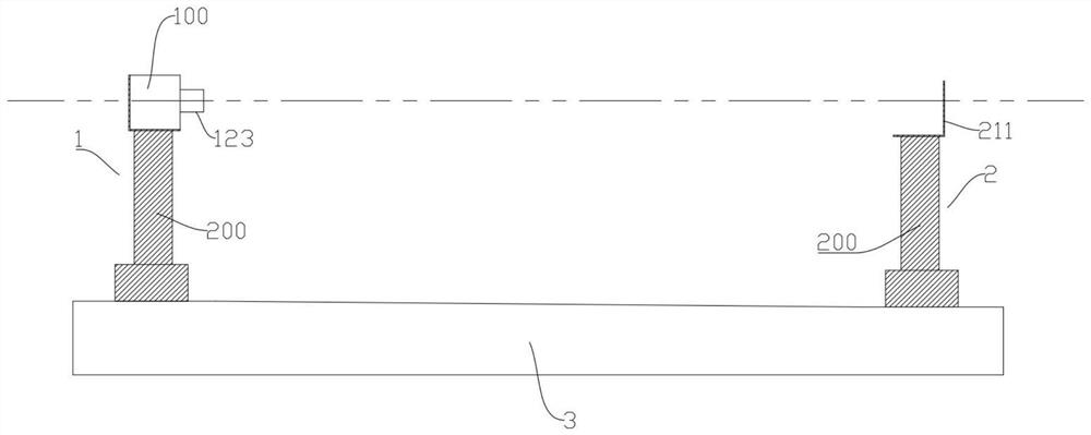
[0045] Such as Figures 1 to 9 As shown, a 3D printing device uses a degree of freedom to print the driving device of the platform, including two oppositely arranged first driving mechanisms and second driving mechanisms;

[0046] The first driving mechanism includes a rotating driving mechanism and a lifting driving mechanism; the second driving mechanism includes a lifting driving mechanism;

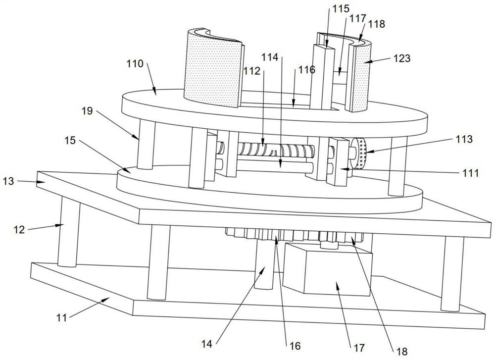
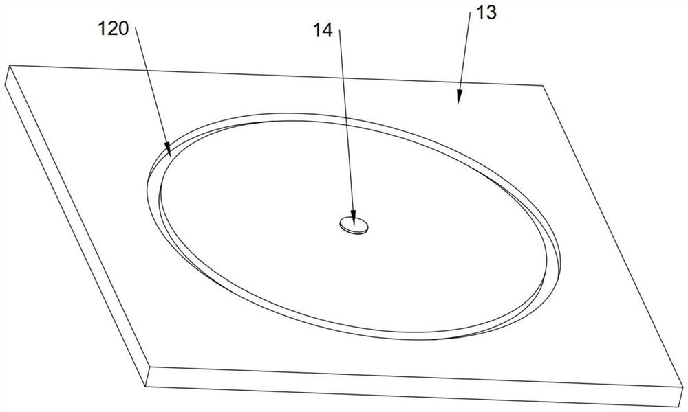
[0047] The rotary drive mechanisms all include a bottom plate, the four corners of the top of the bottom plate are fixed with support legs, the top of the bottom plate is provided with a support plate, the tops of the support legs are fixedly connected with the bottom of the support plate, and the bottom of the bottom plate The top is rotatably connected with a rotating rod through a bearing, the top of the rotating rod runs through the top of the support plate and is fixed with a first disc, the top of the rotating rod is rotatably connected with the supporting plate through a bearing...

Embodiment 2

[0052] Such as Figures 1 to 9 As shown, a 3D printing device uses a degree of freedom to print the driving device of the platform, including two oppositely arranged first driving mechanisms and second driving mechanisms;

[0053] The first driving mechanism includes a rotating driving mechanism and a lifting driving mechanism; the second driving mechanism includes a lifting driving mechanism;

[0054] the rotary drive mechanism, see Figures 2 to 5 , including the base plate, the four corners of the top of the base plate are fixed with support legs, the top of the base plate is provided with a support plate, the tops of the support legs are fixedly connected with the bottom of the support plate, the top of the base plate is connected to the rotating rod through the bearing rotation, the top of the rotating rod It runs through the top of the support plate and is fixed with the first disk. The top of the rotating rod is connected to the supporting plate through bearings. The s...


PUM


Abstract

The invention discloses a driving device of a degree-of-freedom printing base table for 3D printing equipment. The driving device comprises a first driving mechanism and a second driving mechanism which are oppositely arranged. The first driving mechanism comprises a rotary driving mechanism and a lifting driving mechanism; the second driving mechanism comprises a lifting driving mechanism; each lifting driving mechanism comprises an L-shaped fixing plate, a hydraulic rod and a hydraulic cylinder which are sequentially arranged from top to bottom; a horizontal part of the L-shaped fixing plateof the lifting driving mechanism of the first driving mechanism is connected to the upper end of the hydraulic rod, and a vertical part is connected with a bottom plate of the rotary driving mechanism; and a horizontal part of the L-shaped fixing plate of the lifting driving mechanism of the second driving mechanism is connected to the upper end of the hydraulic rod, and a supporting bearing is arranged in the middle of a vertical part. The driving device is suitable for being used as a long-strip-shaped (or called as a long-strip-shaped base shaft) printing base table, in this way, workpieces are formed from inside to outside, all layers are located on the same radius, printing of a plurality of parts can be completed on one printing base table, and the working efficiency is high.

Description

technical field [0001] The invention relates to the technical field of SLM equipment, in particular to a driving device for a 3D printing equipment printing platform with degrees of freedom. Background technique [0002] Selective laser melting (SLM) metal 3D printing technology (Selective laser melting, SLM) uses a precise focus spot to quickly melt the pre-laid layers of metal powder, and can almost directly obtain functional parts with arbitrary shapes and complete metallurgical bonding. The density can reach nearly 100%. It is a rapid prototyping technology with great development prospects, especially in aerospace, medical, automobile, mold and other fields, which has extremely important application prospects. [0003] Chinese Invention Patent No. CN201720583224.9 provides a fast leveling device for the base of SLM equipment. The base shaft can move up and down, but its processing technology is printed layer by layer from top to bottom. All grow axially, limited by diam...

Claims


Application Information

Patent Timeline
Patent Type & Authority Applications(China)
IPC IPC(8): B22F3/105B33Y30/00
CPCB33Y30/00
Inventor 韩品连
Owner ZHEJIANG YIDONG TECH CO LTD
Why Eureka
Try Eureka