Polishing device used for mechanically machining accessories

A technique for polishing devices and mechanical accessories, which is applied in the direction of grinding/polishing safety devices, grinding drive devices, metal processing equipment, etc., which can solve the problems of pipe movement, low polishing efficiency, and reduce one-time polishing area, so as to improve polishing The effect of high efficiency and polishing efficiency

Active Publication Date: 2020-12-04
山东聊城中泰表业有限公司
View PDF6 Cites 1 Cited by
  • Summary
  • Abstract
  • Description
  • Claims
  • Application Information

AI Technical Summary

Problems solved by technology

[0004] In order to solve the problems raised in the above-mentioned background technology, the object of the present invention is to provide a polishing device for mechanical parts processing, which has the advantage of high polishing efficiency, and solves the problem that the existing pipe polishing device clamps and polishes the pipe, so that it cannot be polished during polishing. The pipe is moved to reduce the one-time polishing area, and the polishing position needs to be changed manually, resulting in low polishing efficiency

Method used


Image

  • Polishing device used for mechanically machining accessories
  • Polishing device used for mechanically machining accessories
  • Polishing device used for mechanically machining accessories

Examples


Embodiment Construction

[0053] The following will clearly and completely describe the technical solutions in the embodiments of the present invention with reference to the accompanying drawings in the embodiments of the present invention. Obviously, the described embodiments are only some, not all, embodiments of the present invention. Based on the embodiments of the present invention, all other embodiments obtained by persons of ordinary skill in the art without making creative efforts belong to the protection scope of the present invention.

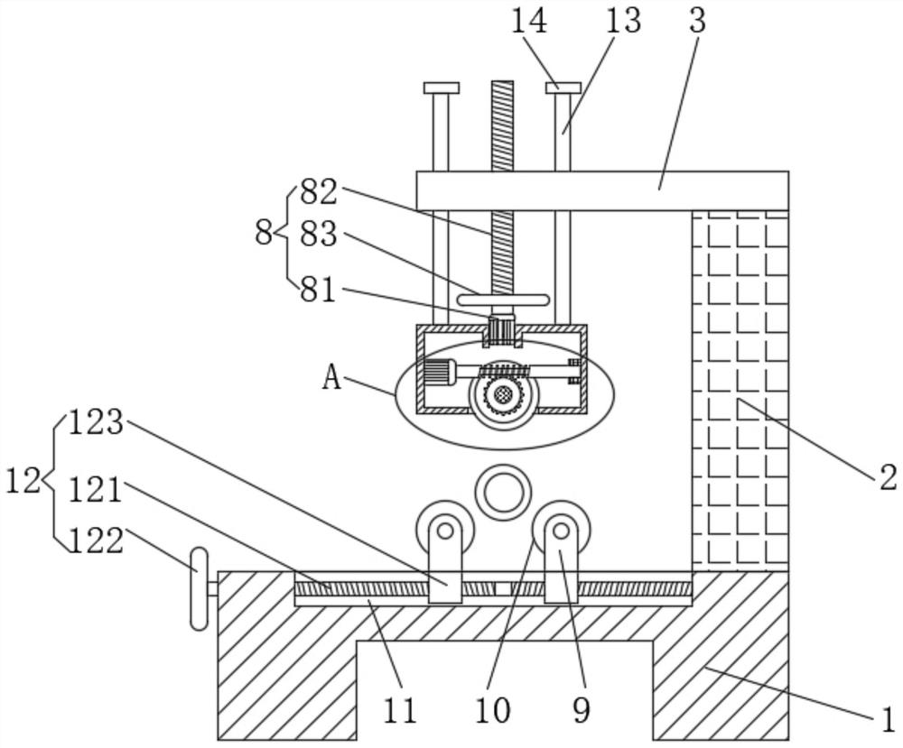
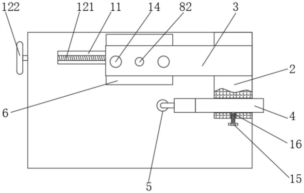
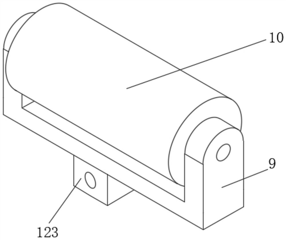
[0054] Such as Figure 1 to Figure 5 As shown, a polishing device for mechanical parts processing provided by the present invention includes a workbench 1, a fixed frame 2 is fixedly connected to the right side of the top of the workbench 1, a top plate 3 is fixedly connected to the top of the fixed frame 2, and the left side of the fixed frame 2 The front side of the side bottom is slidingly installed with a polishing motor 4, the output end of the polishing ...


PUM


Abstract

The invention discloses a polishing device used for mechanically machining accessories. The polishing device comprises a working table. A fixing frame is fixedly connected to the right side of the topof the working table. A top plate is fixedly connected to the top of the fixing frame. A polishing motor is installed on the front side of the bottom of the left side of the fixing frame in a slidingmanner. A polishing head is fixedly connected to the output end of the polishing motor. An adjusting box is arranged at the bottom of the top plate. A uniform polishing transmission mechanism is fixedly connected to the left side of the inner wall of the adjusting box. According to the polishing device, by means of cooperative use of the working table, the fixing frame, the top plate, the polishing motor, the polishing head, the adjusting box, the uniform polishing transmission mechanism, a height adjusting mechanism, an adjusting frame, a supporting cylinder, a sliding groove and a horizontal adjusting assembly, the problems that an existing pipe polishing device clamps, fixes and polishes a pipe, the pipe cannot be moved during the polishing period, the one-time polishing area is reduced, the polishing position needs to be changed manually, and as a result, the polishing efficiency is low are solved, and the polishing device has the advantage of being high in polishing efficiency.

Description

technical field [0001] The invention relates to the technical field of polishing devices, in particular to a polishing device for machining mechanical parts. Background technique [0002] Machining refers to the process of changing the shape, size or performance of the workpiece through a mechanical device. According to the difference in processing methods, it can be divided into cutting processing and pressure processing. When processing pipes, the outer wall of the pipe needs to be polished by a polishing machine. Polishing work. [0003] The problems existing in the existing pipe polishing device are: the pipe is clamped and polished, so that the pipe cannot be moved during polishing, which reduces the one-time polishing area, and the polishing position needs to be manually changed, resulting in low polishing efficiency. Contents of the invention [0004] In order to solve the problems raised in the above-mentioned background technology, the object of the present inven...

Claims


Application Information

Patent Timeline
Patent Type & Authority Applications(China)
IPC IPC(8): B24B29/08B24B55/06B24B49/12B24B51/00B24B47/12B24B41/06B24B55/00B24B47/22
CPCB24B29/08B24B41/067B24B47/12B24B47/22B24B49/12B24B51/00B24B55/00B24B55/06
Inventor 吴洁华
Owner 山东聊城中泰表业有限公司
Why Eureka
Try Eureka