Electric wrench for engraving machine tool rod

An electric wrench and tool rod technology, applied in the field of wrenches, can solve the problems of difficult operation of the wrench and poor clamping effect of the tool rod, and achieve the effects of avoiding slippage, increasing the clamping force and increasing the frictional resistance.

Inactive Publication Date: 2020-12-04
西安致开工业自动化工程有限公司
View PDF1 Cites 1 Cited by
  • Summary
  • Abstract
  • Description
  • Claims
  • Application Information

AI Technical Summary

Problems solved by technology

[0006] The purpose of the present invention is to solve the problem that the wrench used for the tool bar of the engraving machine in the prior art is

Method used


Image

  • Electric wrench for engraving machine tool rod
  • Electric wrench for engraving machine tool rod
  • Electric wrench for engraving machine tool rod

Examples


Embodiment 1

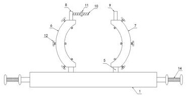
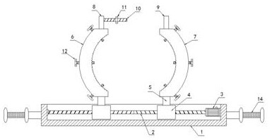
[0024] Embodiment 1, with reference to figure 1 and 2 , an electric wrench for an engraving machine tool bar, comprising a fixed plate 1, the left and right sides of the fixed plate 1 are fixedly provided with handles 14, the upper side of the fixed plate 1 is provided with a bar-shaped groove horizontally, and the inside of the bar-shaped groove A two-way screw rod 2 is arranged horizontally, the left end of the two-way screw rod 2 is rotationally connected with the left side of the bar-shaped groove through a rolling bearing, and a motor 3 is fixed on the right side wall of the bar-shaped groove. The motor 3 adopts a stepping motor, and the model is TB5128FTG , the output end of the motor 3 is fixedly connected to the right end of the two-way screw rod 2 through a coupling, and two moving blocks 4 are arranged for symmetrical sliding inside the strip groove, and the side walls of the two moving blocks 4 pass through the first threaded hole and the The second threaded hole i...

Embodiment 2

[0025] Embodiment 2, with reference to figure 2 , its fastening mechanism includes a first fixed block 8, a second fixed block 9, a one-way screw 10 and a fastening nut 11, the first fixed block 8 is fixedly arranged on the upper end of the first arc splint 6, and the second fixed block The block 9 is fixedly arranged on the upper end of the second arc splint 7, and the one-way screw mandrel 10 is fixedly arranged on the right side wall of the first fixed block 8 in the transverse direction, and the side wall of the second fixed block 9 is provided with a set for the one-way screw mandrel. 10 passes through the mounting hole, and the fastening nut 11 is threaded on the rod wall of the one-way screw rod 10 .

Embodiment 3

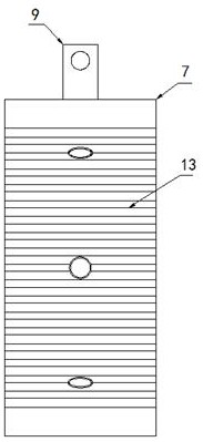
[0026] Embodiment 3, with reference to image 3 , the side walls of its first arc-shaped splint 6 and the second arc-shaped splint 7 are provided with a plurality of evenly distributed third threaded holes, and the internal threads of the third threaded holes are provided with jacking bolts 12, the first arc Both the inner side walls of the curved splint 6 and the second curved splint 7 are provided with anti-slip lines 13 to increase the clamping stability between the first curved splint 6 and the second curved splint 7 and the tool bar.


PUM


Abstract

The invention relates to the technical field of wrenches, and discloses an electric wrench for an engraving machine tool rod. The electric wrench comprises a fixing plate, a strip-shaped groove is transversely formed in the upper side of the fixing plate, a bidirectional screw rod is transversely arranged in the strip-shaped groove, the left end of the bidirectional screw rod is rotationally connected with the left side of the strip-shaped groove through a rolling bearing, a motor is fixedly arranged on the right side wall of the strip-shaped groove, the output end of the motor is fixedly connected with the right end of the bidirectional screw rod through a coupler, two moving blocks are symmetrically arranged in the strip-shaped groove in a sliding mode, the side walls of the two moving blocks are in threaded connection with the two sides of the rod wall of the bidirectional screw rod through a first threaded hole and a second threaded hole respectively, and connecting rods are fixedly arranged on the upper sides of the two moving blocks. According to the electric wrench, the operation intensity of workers is reduced, and a first arc-shaped clamping plate and a second arc-shaped clamping plate can be guaranteed to stably clamp the tool rod, so that the dismounting and mounting efficiency of the tool rod is improved.

Description

technical field [0001] The invention relates to the technical field of wrenches, in particular to an electric wrench for an engraving machine tool bar. Background technique [0002] At present, two extended spanners are usually used for the disassembly and assembly of the ultrasonic tool bar, one is stuck on the horn and the other is stuck on the tool bar, and the tool bar is disassembled and assembled with two hands or two people at the same time. Because the horn is fixed on the equipment, when disassembling the tool bar, the wrench stuck on the horn is easy to twist the horn, and using two bulky extended wrenches at the same time is not conducive to operation, which increases the operating strength of the staff , and the clamping effect on the tool rod is not good, so it is easy to cause the screw not to be tightened or tightened too tightly. [0003] Among them, the patent number is CN206812683U, which discloses a tool bar wrench for ultrasonic engraving machine, includ...

Claims


Application Information

Patent Timeline
IPC IPC(8): B25B11/00
CPCB25B11/02
Inventor 白琳
Owner 西安致开工业自动化工程有限公司
Why Eureka
Try Eureka