
Multi-functional clamp for mechanical manufacturing

A mechanical manufacturing and multi-functional technology, applied in the field of workpiece processing, can solve problems such as single function, complicated fixture operation, single fixture function, etc.

Inactive Publication Date: 2020-12-04
JIANGSU SECURITY TECH CARRER ACADEMY
View PDF7 Cites 2 Cited by
  • Summary
  • Abstract
  • Description
  • Claims
  • Application Information

AI Technical Summary

Problems solved by technology

[0003] With the emergence of parts with various complex structures and special process requirements, the requirements for fixtures are getting higher and higher. However, the existing fixtures have a single function. Generally, the bottom and both sides of the original parts to be processed are wrapped in fixtures. Inside, the upper end surface is exposed for processing. If other surfaces need to be processed, the original to be processed needs to be removed, and then the surface to be processed is reinstalled facing upward. This kind of fixture is complicated to operate and has a single function.

Method used


Image

  • Multi-functional clamp for mechanical manufacturing
  • Multi-functional clamp for mechanical manufacturing
  • Multi-functional clamp for mechanical manufacturing

Examples


Embodiment Construction

[0031] A specific embodiment of the present invention will be described in detail below in conjunction with the accompanying drawings, but it should be understood that the protection scope of the present invention is not limited by the specific embodiment.

[0032] In describing the present invention, it should be understood that the terms "center", "longitudinal", "transverse", "length", "width", "thickness", "upper", "lower", "front", " Rear", "Left", "Right", "Vertical", "Horizontal", "Top", "Bottom", "Inner", "Outer", "Axial", "Radial", "Circumferential" The orientation or positional relationship indicated by etc. is based on the orientation or positional relationship shown in the drawings, and is only for the convenience of describing the technical solution of the present invention and simplifying the description, rather than indicating or implying that the referred device or element must have a specific orientation, Constructed and operative in a particular orientation a...


PUM


Abstract

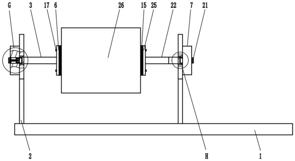
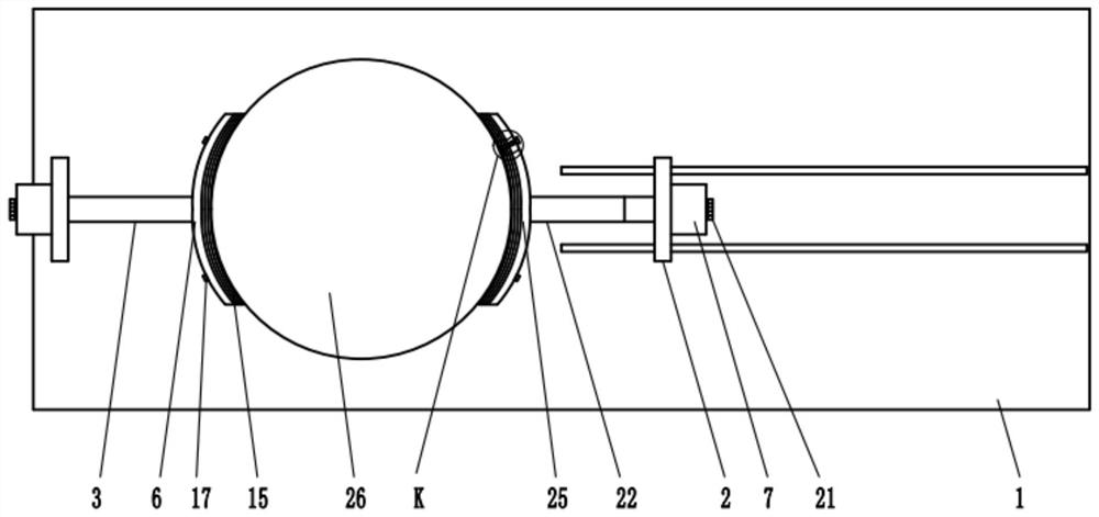
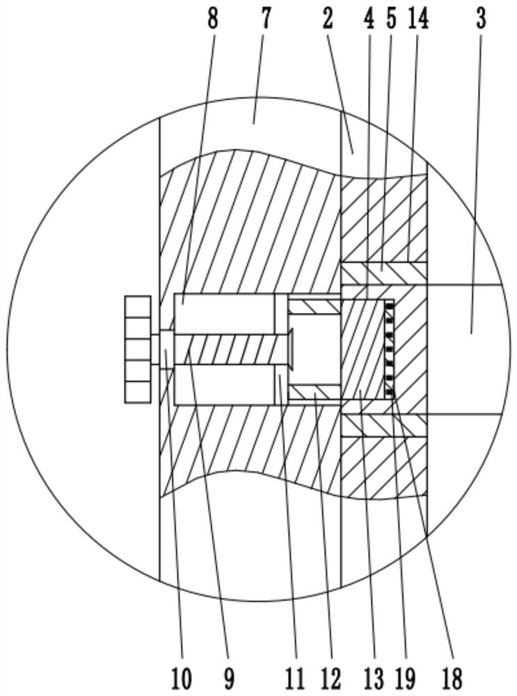
The invention relates to the technical field of workpiece machining, and discloses a multi-functional clamp for mechanical manufacturing. The multi-functional clamp comprises a bottom plate, two sideplates, a fixed connecting rod, a telescopic rod, a fixed plate, a threaded rod, a movable plate, a sleeve and a clamping block, the bottom plate is fixed on an operating table, the two side plates are perpendicular to the bottom plate and are respectively provided with a first through hole, and the fixed connecting rod is parallel to the bottom plate; and the telescopic rod and the fixed connecting rod are symmetrically arranged, the fixed plate is fixedly connected to the outer side walls of the two side plates, the threaded rod is hinged to the fixed plate through a third bearing, the movable plate is in threaded connection with the periphery of the threaded rod, the sleeve sleeves the periphery of the threaded rod, and the clamping block is fixedly connected to the second end of the sleeve and is located on the inner side of the threaded rod all the time and matched with a first groove in size. Fixing of the position of a part to be machined is realized by clamping the clamping block into a clamping groove, machining of multiple machining faces is achieved, and for the to-be-machined parts with different widths, the to-be-machined parts with various sizes can be clamped by adjusting the distance between a first clamping part and a second clamping part.

Description

technical field [0001] The invention relates to the technical field of workpiece processing, in particular to a multifunctional fixture for mechanical manufacturing. Background technique [0002] Fixture refers to the device used to fix the processing object in the process of mechanical manufacturing so that it can occupy the correct position to accept construction or inspection. It is also called fixture. In a broad sense, any process in the process is used to quickly and The device that installs the workpiece conveniently and safely can be called a fixture. [0003] With the emergence of parts with various complex structures and special process requirements, the requirements for fixtures are getting higher and higher. However, the existing fixtures have a single function. Generally, the bottom and both sides of the original parts to be processed are wrapped in fixtures. Inside, the upper end surface is exposed for processing. If other surfaces need to be processed, the or...

Claims


Application Information

Patent Timeline
IPC IPC(8): B25B11/00
CPCB25B11/00
Inventor 陆彩满
Owner JIANGSU SECURITY TECH CARRER ACADEMY
Learn More