
Plane sucker, conveying equipment and medical robot

A suction cup and plane technology, applied in the field of end effectors, can solve the problems of poor control accuracy and high energy consumption of end effectors, and achieve the effects of energy saving and high control accuracy

Active Publication Date: 2020-12-04
SHENZHEN INST OF ADVANCED TECH CHINESE ACAD OF SCI
View PDF8 Cites 0 Cited by
  • Summary
  • Abstract
  • Description
  • Claims
  • Application Information

AI Technical Summary

Problems solved by technology

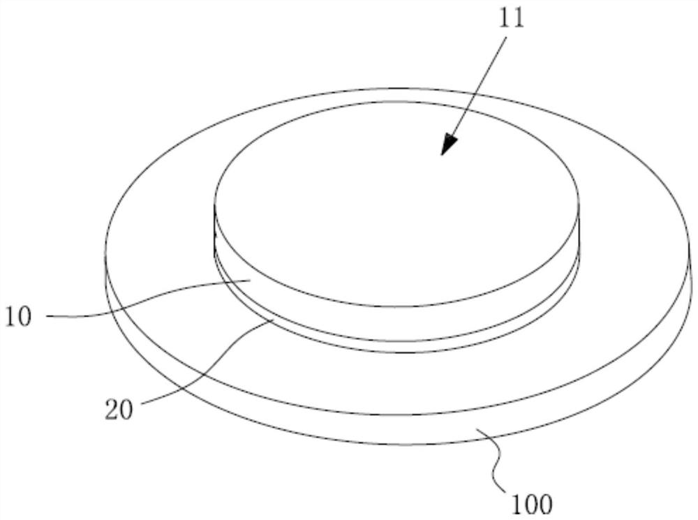
[0003] The purpose of the present invention is to provide a plane suction cup, transmission equipment, and medical robot, aiming to solve the problems of high energy consumption and poor control precision of existing end effectors

Method used


Image

  • Plane sucker, conveying equipment and medical robot
  • Plane sucker, conveying equipment and medical robot
  • Plane sucker, conveying equipment and medical robot

Examples


Embodiment Construction

[0035] Embodiments of the present invention are described in detail below, examples of which are shown in the drawings, wherein the same or similar reference numerals designate the same or similar elements or elements having the same or similar functions throughout. The embodiments described below by referring to the figures are exemplary and are intended to explain the present invention and should not be construed as limiting the present invention.

[0036] In describing the present invention, it should be understood that the terms "length", "width", "upper", "lower", "front", "rear", "left", "right", "vertical", The orientation or positional relationship indicated by "horizontal", "top", "bottom", "inner", "outer", etc. are based on the orientation or positional relationship shown in the drawings, and are only for the convenience of describing the present invention and simplifying the description, rather than Nothing indicating or implying that a referenced device or element...


PUM


Abstract

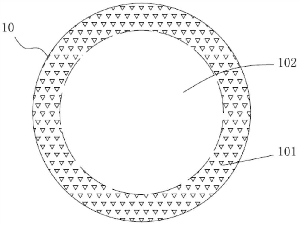
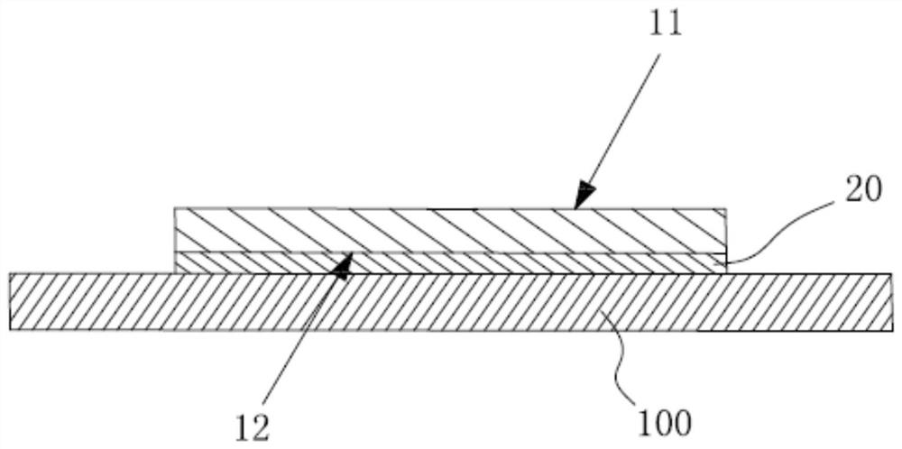
The invention belongs to the technical field of end effectors, and particularly relates to a plane sucker, conveying equipment and a medical robot. The plane sucker comprises a base body (10), whereinthe base body (10) is provided with a first side face (11) and a second side face (12), the second side face (12) is provided with a circumferential connecting area (101) and a non-connecting area (102), and the connecting area (101) surrounds the non-connecting area (102); and a dielectric elastomer driver (20), wherein the dielectric elastomer driver (20) is in a flat plate shape in an initialstate, the dielectric elastomer driver (20) is arranged on the second side face (12), the connecting area (101) is fixedly connected with the dielectric elastomer driver (20) in a sealed manner, and apositive terminal (201) and a negative terminal (202) which are used for loading voltages are led out of the dielectric elastomer driver (20). By means of the technical scheme, the problems that an existing end effector is high in energy consumption and poor in control precision can be solved.

Description

technical field [0001] The invention belongs to the technical field of end effectors, and in particular relates to a plane suction cup, a transmission device and a medical robot. Background technique [0002] The end effector is a mechanical component that is frequently used in the industrial field. It is mainly used for grabbing objects in industrial production. The end effectors commonly used in the industry mainly include electromagnetic, hydraulic and pneumatic, and their combinations. , the existing pneumatic end effector mainly uses the air pressure control system to connect the driving device through the air pipe, so the air pressure leakage caused by the friction between the gas and the air pipe and the gas channel during the pneumatic driving process will affect the control accuracy and lead to the adsorption of the end effector The force is uncontrollable. At the same time, the pneumatic drive requires a pneumatic system to form a negative pressure environment, and...

Claims


Application Information

Patent Timeline
Patent Type & Authority Applications(China)
IPC IPC(8): B25J7/00B25J15/06B25J19/00B25J11/00
CPCB25J7/00B25J11/00B25J15/0683B25J19/00
Inventor 高兴曹崇景王磊
Owner SHENZHEN INST OF ADVANCED TECH CHINESE ACAD OF SCI
Learn More