Telephone receiver line and rolling rod rolling system and method

A technology for telephone receivers and reels, which is applied in metal processing, household components, household appliances, etc., can solve the problems of poor clamping effect of reeling rods, improve cutting quality and cutting efficiency, improve coordination, and improve stability. sexual effect

Inactive Publication Date: 2020-12-04
孙广静
View PDF5 Cites 1 Cited by
  • Summary
  • Abstract
  • Description
  • Claims
  • Application Information

AI Technical Summary

Problems solved by technology

[0005] The object of the present invention is to solve the above-mentioned problem of poor clamping effect of the existing telephone receiver cord coiling rod, and to provide a clamping and rotating device for the telephone receiver cord coiling rod, which drives the clamping push rod to Clamping is realized on the inner side; one end of the rolling rod can be better clamped and limited by the clamping limit sleeve; the hard contact between the clamping rod and the clamping push rod is reduced by the clamping spring, and the lifting At the same time of the clamping effect, the cooperation between the clamping rod and the clamping push rod is also improved...

Method used


Image

  • Telephone receiver line and rolling rod rolling system and method
  • Telephone receiver line and rolling rod rolling system and method
  • Telephone receiver line and rolling rod rolling system and method

Examples


Embodiment Construction

[0029] The specific implementation manner of the present invention will be described in detail below in conjunction with the accompanying drawings.

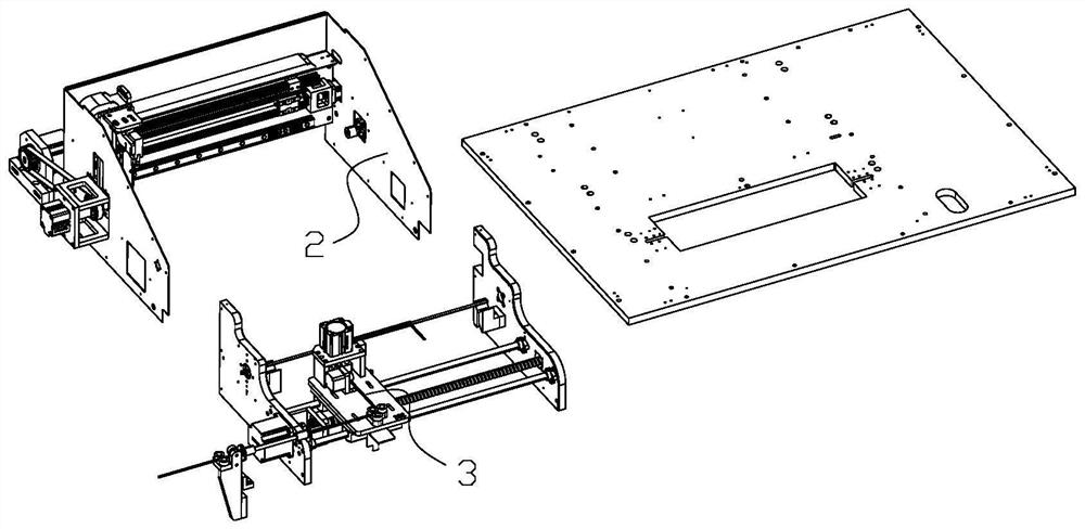
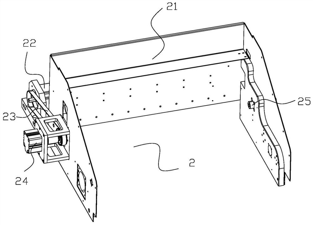
[0030] Such as figure 1 Shown, a kind of telephone receiver line and rolling bar coiling system, this system comprises frame and the rolling bar clamping rotating device 2 on it and telephone receiver line feeding clamping and cutting device 3; Rolling bar clamp The tightening and rotating device 2 is used to clamp the two ends of the rolling rod and drive the rolling rod to rotate when rolling; the telephone handset wire feeding clamping and cutting device 3 includes a telephone handset wire feeding assembly 31, a telephone handset wire clamp Tight assembly 32 and telephone handset wire cutting assembly 33; Telephone handset wire feeding assembly 31 is positioned at the front side of rolling bar clamping rotating device 2, and telephone handset wire feeding assembly 31 is used for conveying and feeding telephone handset wire, te...


PUM


Abstract

The invention belongs to the technical field of telephone receiver line automatic production, in particular to a telephone receiver line and rolling rod rolling system and method. The telephone receiver line and rolling rod rolling system comprises a rolling rod clamping and rotating device and a telephone receiver line feeding, clamping and cutting device, wherein the rolling rod clamping and rotating device comprises a U-shaped support, a rolling rod rotating motor, a conveying belt assembly, a first rolling rod clamping cylinder and a second rolling rod clamping cylinder; the U-shaped support is arranged on a frame and located on the front side of a rolling rod feeding transfer device; the opening of the U-shaped support faces forwards; the rolling rod rotating motor is arranged on theframe through a rotating motor support, and located on the left side of the U-shaped support; one end of the conveying belt assembly is arranged on a moving part of the rolling rod rotating motor in asleeving mode; the other end of the conveying belt assembly is matched with the first rolling rod clamping cylinder; the first rolling rod clamping cylinder is arranged in the middle of the left sideof the U-shaped support; and the second rolling rod clamping cylinder is arranged in the middle of the right side of the U-shaped support. The telephone receiver line and rolling rod rolling system and method have the advantages that the clamping stability of a rolling rod and the rotation effectiveness of the rolling rod are improved.

Description

technical field [0001] The invention belongs to the technical field of automatic production of telephone handset cords, and in particular relates to a system and method for winding a telephone handset cord and a rolling rod. Background technique [0002] The telephone handset line is used to connect the telephone and the handset. The telephone handset line is spiral, and the spiral telephone handset line is convenient to realize expansion and contraction when the telephone is in use, and it is convenient to lengthen the distance between the microphone and the telephone when making a call , At the end of the call, it is convenient to shrink the telephone receiver line, reduce the occupied area, and also facilitate the storage of the telephone receiver line. [0003] The rolling rod, telephone handset wire and splint are needed in the production process of the telephone handset wire rolling; the telephone handset wire is fixed at one end of the telephone handset wire through t...

Claims


Application Information

Patent Timeline
IPC IPC(8): B29C53/12B29C53/80B26D1/06B29L31/34
CPCB26D1/06B29C53/12B29C53/80B29L2031/3431
Inventor 孙广静徐盼盼徐平丽
Owner 孙广静
Why Eureka
Try Eureka