An auxiliary device for applying glue and sticking the tip of a writing brush
An auxiliary device and gluing technology, which can be applied to devices that apply liquid to the surface, coatings, other ink pens, etc., can solve the problems of high failure rate of brushes, waste, and easy sticking of glue on the pen, so as to achieve a beautiful appearance. , the effect of increasing the pass rate and avoiding errors
- Summary
- Abstract
- Description
- Claims
- Application Information
AI Technical Summary
Problems solved by technology
Method used
Image
Examples
Embodiment 1
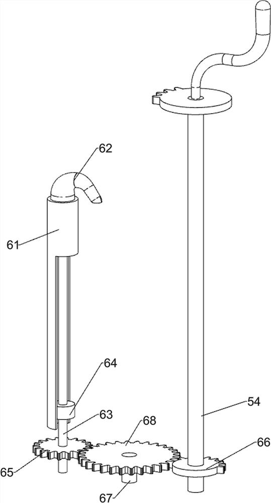
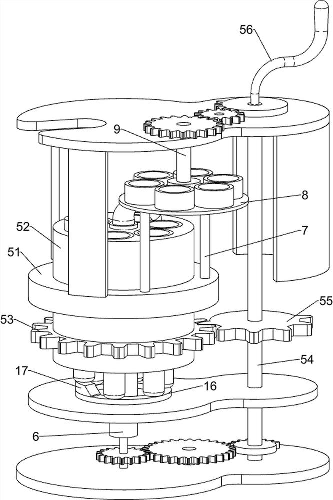
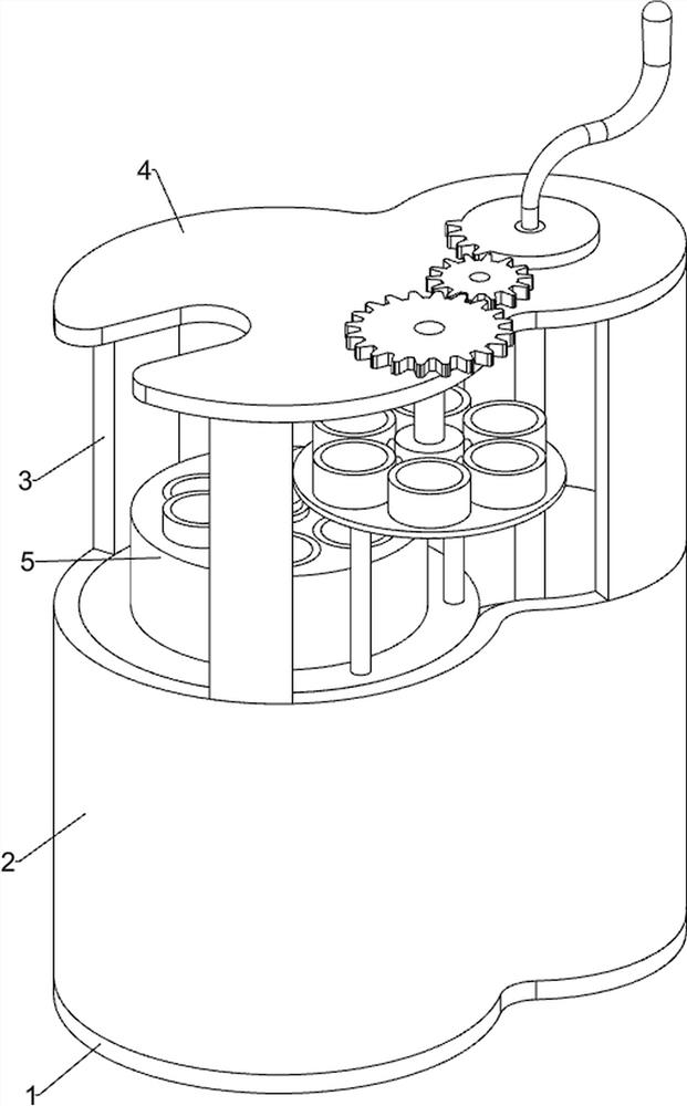
[0037] A writing brush gluing and sticking pen head auxiliary device, such as figure 1 and figure 2 As shown, it includes a base 1, a casing 2, a support block 3, a top plate 4, a rotating mechanism 5 and a glue extrusion mechanism 6. The top of the base 1 is provided with a casing 2, the top of the casing 2 is evenly spaced with a support block 3, and the top of the support block 3 is provided with A top plate 4 is connected therebetween, and a rotating mechanism 5 is rotatably connected between the top right side of the top plate 4 and the top of the base 1, and the rotating mechanism 5 is located inside the casing 2, and the rotating mechanism 5 is connected with the top of the base 1 in a rotating manner. Glue mechanism 6.
[0038] When the staff needs to glue the brush pen holder, first the staff place the pen holder in the parts in the rotating mechanism 5 one by one, and then the staff manually rotate the parts in the rotating mechanism 5, so that the rotating mechani...
Embodiment 2
[0044] On the basis of Example 1, as figure 2 and Figure 4 As shown, it also includes a support column 7, a guide rail 8, a second rotating shaft 9, a disc 10, a cylinder 11, a fourth circular gear 12, a third rotating shaft 13, a fifth circular gear 14 and a third missing gear 15, The top right side of the annular slide rail 51 is provided with two support columns 7, the tops of the support columns 7 are connected with guide rails 8, the front side of the top plate 4 is rotatably connected with a second rotating shaft 9, and the lower part of the second rotating shaft 9 is provided with a disc 10 , the outer wall of the disc 10 is evenly spaced with a cylinder 11, and the bottom of the cylinder 11 is in contact with the top of the guide rail 8, the upper part of the second shaft 9 is provided with a fourth circular gear 12, and the fourth circular gear 12 is located above the top plate 4, A third rotating shaft 13 is rotatably connected to the top right side of the top pla...
Embodiment 3
[0047] On the basis of Example 2, as figure 2 As shown, it also includes annular spacers 16 and bumps 17, a transverse plate is arranged inside the casing 2, and the transverse plate is connected to the lower part of the compression cylinder 61, the transverse plate is rotatably connected with the transmission shaft 54, and the left side of the top of the transverse plate is provided with There is an annular spacer block 16 , and the annular spacer block 16 is located below the rotating material cylinder 52 , and a convex block 17 is provided on the left side of the top of the annular spacer block 16 .
[0048] When the rotating barrel 52 rotates 60 degrees clockwise on the annular slide rail 51, the rotating barrel 52 rotates 60 degrees clockwise to drive the pen barrel to rotate 60 degrees clockwise, and at the same time drive the brush that has finished sticking the pen to rotate 60 degrees clockwise. When the brush with the sticking end is rotated clockwise to contact wit...
PUM
 Abstract
Description
Claims
Application Information
 - R&D
- Intellectual Property
- Life Sciences
- Materials
- Tech Scout
- Unparalleled Data Quality
- Higher Quality Content
- 60% Fewer Hallucinations
Browse by: Latest US Patents, China's latest patents, Technical Efficacy Thesaurus, Application Domain, Technology Topic, Popular Technical Reports.
© 2025 PatSnap. All rights reserved.Legal|Privacy policy|Modern Slavery Act Transparency Statement|Sitemap|About US| Contact US: help@patsnap.com


