A built-in adjustable position suspension handle device for buses

A bus, built-in technology, applied to the special position of the vehicle, vehicle components, transportation and packaging, etc., can solve the problems of not being able to stand firmly, discomfort when touching the body, danger, etc., and achieve a practical, comfortable and safe effect

Active Publication Date: 2022-02-11
ZHEJIANG AGRI BUSINESS COLLEGE
View PDF7 Cites 0 Cited by
  • Summary
  • Abstract
  • Description
  • Claims
  • Application Information

AI Technical Summary

Problems solved by technology

[0002] When taking a bus body, sometimes the seats are full and people need to stand and ride. Handles are installed on the corridors of the bus body, but the height of the handles is fixed. People's heights are different, and the fixed height handles are not suitable for different heights. If the bus body is too crowded and short people cannot reach the uprights, it is very dangerous because the handles are too high and they cannot stand firmly; secondly, because the number of handles is fixed and the positions of adjacent handles are fixed, The use of passengers of different sizes will cause physical contact and discomfort

Method used


Image

  • A built-in adjustable position suspension handle device for buses
  • A built-in adjustable position suspension handle device for buses
  • A built-in adjustable position suspension handle device for buses

Examples


Embodiment 1

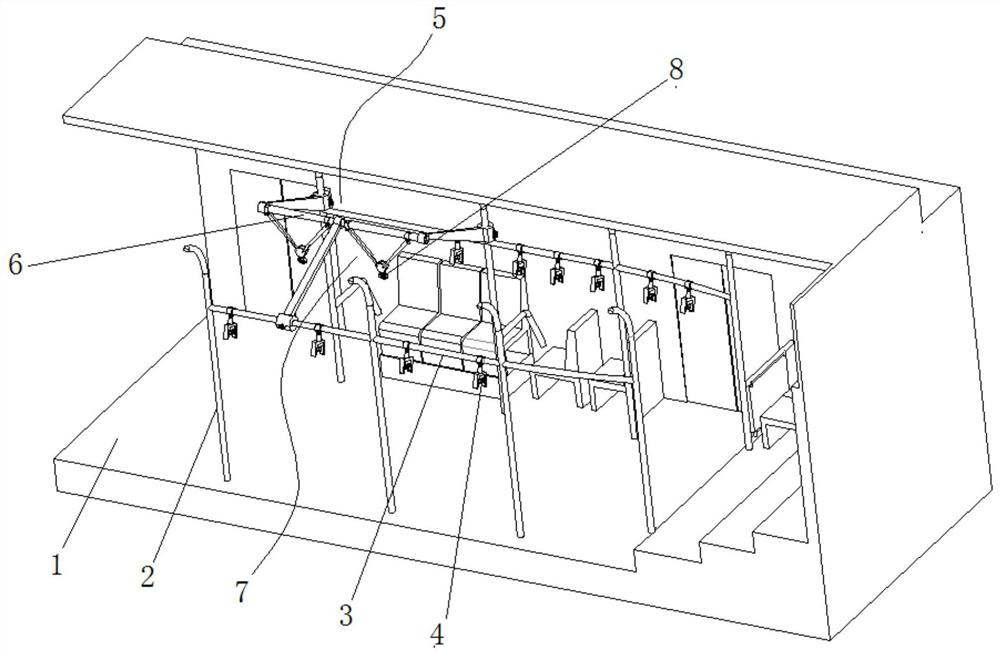
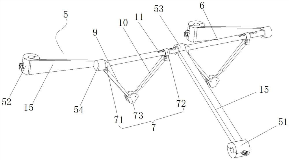
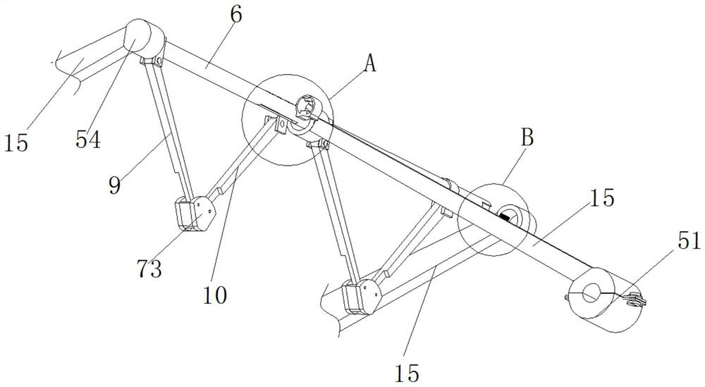
[0028] Embodiment one, such as Figure 1-7 Shown: a bus built-in adjustable suspension handle device, including a bus body 1, the two sides of the car body 1 are respectively provided with a plurality of uprights 2 at intervals, between two adjacent uprights 2 The upper side of the upper side is respectively connected by the support rod one 3, and the support rod one 3 is provided with a fixed pull handle 4 at intervals, and the corresponding vertical rod 2 and the support rod one 3 on both sides are respectively movably connected with a support member 5, and the inner side of the support member 5 And be positioned at the middle part of car body 1 and be fixedly provided with support bar two 6, support bar two 6 height is higher than support bar one 3 in vertical direction, and support bar two 6 is provided with a plurality of adjustment parts 7, and adjustment part 7 is provided with Active pull handle 8 is arranged.

[0029] as attached Figure 1-2 As shown, a suspension h...

Embodiment 2

[0044] Embodiment two, such as Figure 8-9 Shown: the structure of the connection between the connecting seat 73 and the movable pull handle 8 is different from that of Embodiment 1, and the rest of the structures are the same.

[0045] The inside of connecting seat 73 is hollow, and the lower side is open, and the inner side wall of connecting seat 73 is pivotally connected with running wheel 27 by rotating shaft 26, and a wide rope 21 is wound on the running wheel 27, and the outer side end of wide rope 21 and movable pull handle 8 Link to each other, another wide rope 21 is also connected between the bottom of the connection seat 73 and the movable pull handle 8 (need to have a certain surplus, to coordinate the adjustment of another wide rope 21 degree is applicable).

[0046] A through hole 28 is provided on the connecting seat 73, and the size of the through hole 28 matches the size of the rotating shaft 26. The outer end of the rotating shaft 26 is connected with a stra...


PUM


Abstract

The invention discloses a built-in suspension handle device with adjustable position for a bus. Connected through the support rod one, the upper support rod one is provided with fixed pull handles at intervals, and the corresponding vertical rods on both sides and the support rod one are respectively movably connected with support members, and the inner side of the support member is fixed in the middle of the car body. The second support rod is higher than the first support rod in the vertical direction, and the second support rod is provided with a plurality of adjustment parts. The present invention is a built-in suspension handle device with adjustable position in the bus. The setting of the suspension handle device makes the handles that move horizontally and up and down inside the bus more adaptable to the body shape of the user, and is practical and more comfortable. And safe, and the pull handle of this solution is mainly set in the middle of the bus, which is more suitable for the actual use scene in the bus, and can better disperse passengers.

Description

technical field [0001] The invention relates to the technical field of public facilities, in particular to a built-in, position-adjustable suspension handle device for a bus. Background technique [0002] When taking a bus body, sometimes the seats are full and people need to stand and ride. Handles are installed on the corridors of the bus body, but the height of the handles is fixed. People's heights are different, and the fixed height handles are not suitable for different heights. If the bus body is too crowded and short people cannot reach the uprights, it is very dangerous because the handles are too high and they cannot stand firmly; secondly, because the number of handles is fixed and the positions of adjacent handles are fixed, The use of passengers of different sizes will cause discomfort due to physical contact. [0003] In order to solve the above problems, this case was born. Contents of the invention [0004] (1) Solved technical problems [0005] Aiming a...

Claims


Application Information

Patent Timeline
Patent Type & Authority Patents(China)
IPC IPC(8): B60N3/02
CPCB60N3/02B60N3/026
Inventor 刘晓杰
Owner ZHEJIANG AGRI BUSINESS COLLEGE
Why Eureka
Try Eureka