
Positioning device for concrete corner structure pouring and using method of positioning device

A technology for pouring concrete and positioning device, which is applied in the preparation of building components on site, building construction, and processing of building materials, etc. Avoid section size deviation, improve installation and construction quality, and ensure the effect of hole forming size and use function

Inactive Publication Date: 2020-12-04
SHANGHAI BAOYE GRP CORP
View PDF6 Cites 0 Cited by
  • Summary
  • Abstract
  • Description
  • Claims
  • Application Information

AI Technical Summary

Problems solved by technology

The shear wall is a composite material composed of steel bars and concrete. During the construction process, a large number of formwork needs to be installed to control the size of the wall. The most important point of formwork installation is formwork reinforcement. Because the self-weight of concrete has a large Fluidity often causes problems such as mold expansion and grout leakage in the formwork installed at the corner of the shear wall, which seriously affects the structural section size and use function

Method used


Image

  • Positioning device for concrete corner structure pouring and using method of positioning device
  • Positioning device for concrete corner structure pouring and using method of positioning device

Examples


Embodiment 1

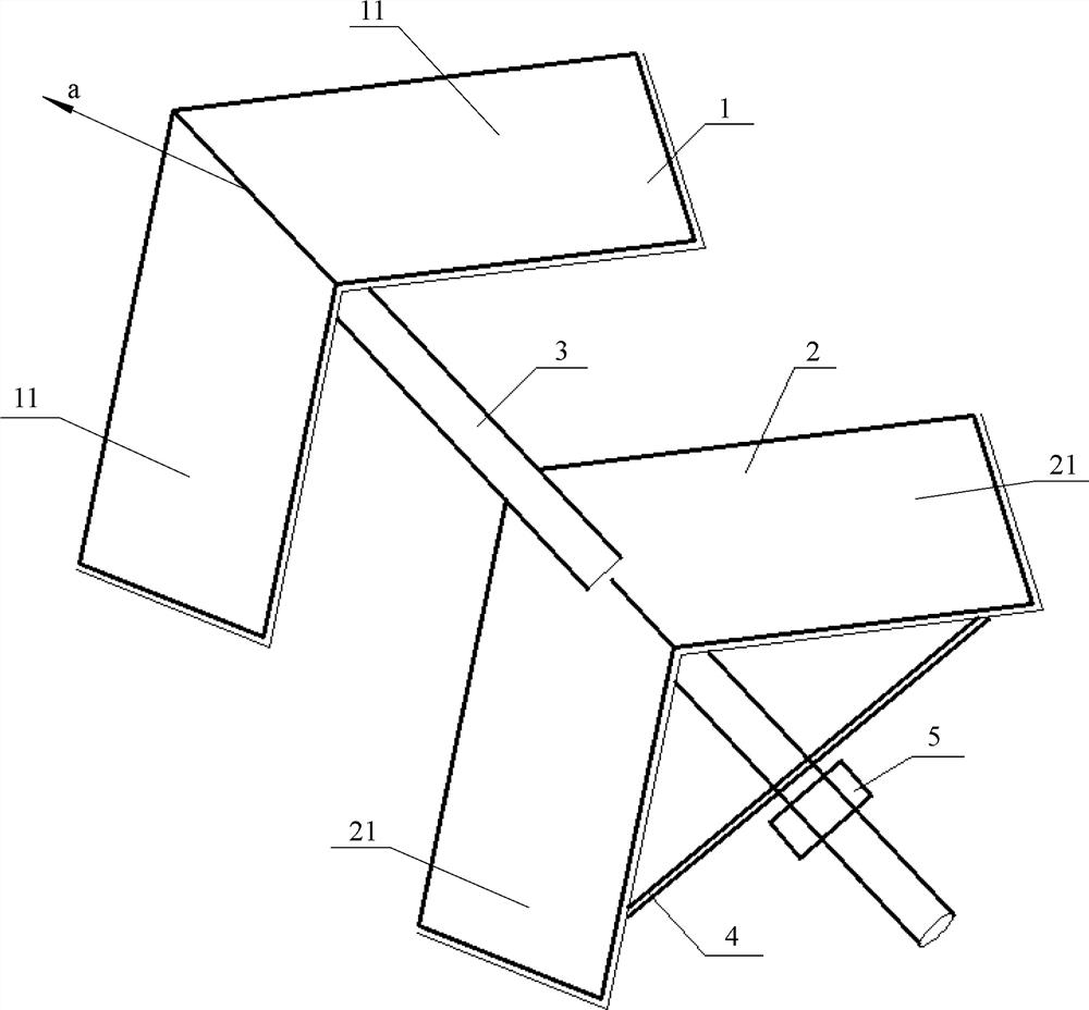
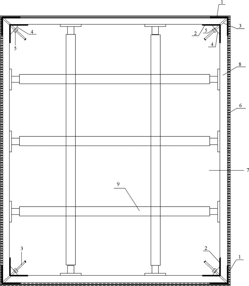
[0025] A positioning device for pouring concrete corner structures, including an end hoop 1, an inner hoop 2, a tie rod 3, a limiting plate 4 and a fastening nut 5, such as figure 1 As shown, the specific structure is:

[0026] The end hoop 1 is composed of two mutually perpendicular end fixing plates 11, each of which uses one side as the end common side to fit and fix each other, and the inner hoop 2 is composed of two mutually perpendicular inner fixing plates 21, each of which uses one side as the inner common side Fitted and fixed to each other, an inner through hole is provided at the midpoint of the inner common side of the inner hoop 2;

[0027] The outer end of the tie rod 3 is fixed at the midpoint of the common side of the concave side of the end hoop 1, and the inner end of the tie rod 3 passes through the inner through hole of the inner hoop 2 so that the inner hoop 2 is movably strung on the tie rod 3. the convex side of ferrule 2 towards the concave side of end...


PUM


Abstract

The invention relates to the field of supporting devices for wallboard forms, in particular to a positioning device for concrete corner structure pouring and a using method of the positioning device.The positioning device for concrete corner structure pouring comprises an end hoop (1) and an inner hoop (2), and is characterized by further comprising a pull rod (3), a limiting plate (4) and a fastening nut (5), wherein the outer end of the pull rod (3) is fixed to the midpoint of the common edge of the end hoop (1), the inner hoop (2) movably sleeves the pull rod (3), the limiting plate (4) movably sleeves the pull rod (3), and the fastening nut (5) is screwed on the pull rod (3). The using method of the positioning device for concrete corner structure pouring is implemented after wall steel bar binding, and is characterized by being sequentially implemented according to the following steps of (1) form splicing; (2) form fixing; (3) pouring; and (4) form removing. According to the device and the method, form erecting is stable, and the construction is rapid.

Description

technical field [0001] The invention relates to the field of supporting devices for wallboard formwork, in particular to a positioning device for pouring concrete corner structures and a method for using the same. Background technique [0002] With the development of building technology, shear walls are widely used due to their good structural properties. The shear wall is a composite material composed of steel bars and concrete. During the construction process, a large number of formwork needs to be installed to control the size of the wall. The most important point of formwork installation is formwork reinforcement. Because the self-weight of concrete has a large Fluidity often causes problems such as mold expansion and grout leakage in the formwork installed at the corner of the shear wall, which seriously affects the structural section size and use function. Contents of the invention [0003] In order to overcome the defects of the prior art and provide a formwork sup...

Claims


Application Information

Patent Timeline
Patent Type & Authority Applications(China)
IPC IPC(8): E04G13/00E04G21/18
CPCE04G13/00E04G21/1858
Inventor 管聪聪李大伟杨虎堂王明涛沈汉兵曾斌
Owner SHANGHAI BAOYE GRP CORP
Learn More