Rail-mounted inspection robot

An inspection robot and track-type technology, applied in the direction of instruments, two-dimensional position/channel control, non-electric variable control, etc., can solve the problems of increased overall weight, inconvenient maintenance, and reduced use effect, and achieve the degree of automation High, light overall weight, improve the effect of use

Pending Publication Date: 2020-12-04
SHANDONG INST OF COMMERCE & TECH
View PDF1 Cites 5 Cited by
  • Summary
  • Abstract
  • Description
  • Claims
  • Application Information

AI Technical Summary

Problems solved by technology

[0004] The above-mentioned type of inspection robot can replace manual on-duty to improve the problems that arise during manual on-duty, but this type of inspection robot uses a stepping servo motor to drive the gear to rotate and mesh with the synchronous toothed belt on the track to drive the robot joints below it. Walking, and the joints of the robot are complex, resulting in a complex structure of this type o

Method used


Image

  • Rail-mounted inspection robot
  • Rail-mounted inspection robot
  • Rail-mounted inspection robot

Examples


Embodiment

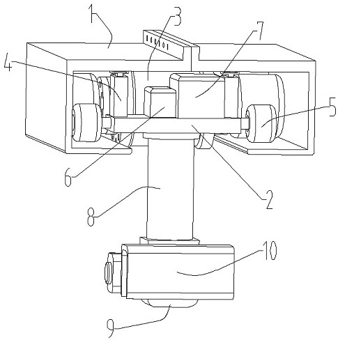
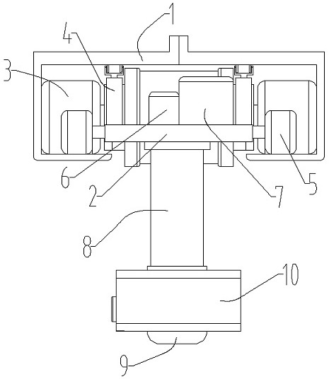
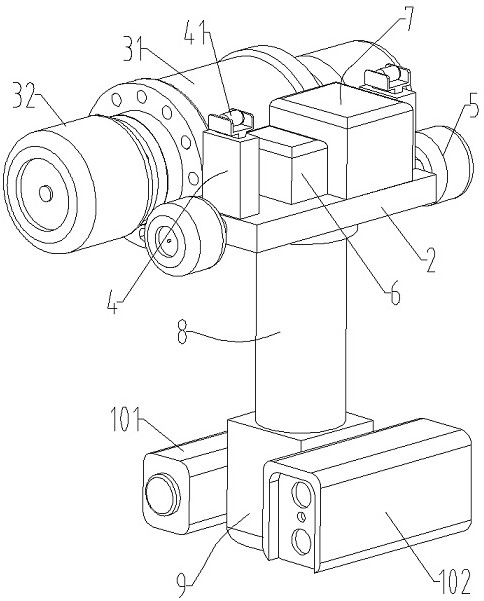
[0037] Example: such as Figure 1-3 As shown, a track-type inspection robot includes a track 1 pre-set according to the travel path, a base plate 2 is arranged inside the track 1, and a mobile joint module 3 for driving the overall movement is set on the base plate 2. The base plate 2 is provided with a pressing wheel device 4 connected to the track 1 for pressing the mobile joint module 3, and a terminal device 10 for monitoring the monitoring area is provided under the substrate 2, and a terminal device 10 is provided on the substrate 2 for A joint module that drives the end device 10 to move and rotate in multiple directions.

[0038] Such as Figure 1-2 with Figure 4 As shown, the track 1 is composed of a first track body 11 and a second track body 12, the first track body 11 and the second track body 12 are arranged oppositely, and the first track body 11 and the second track body 12 They are fixedly connected by connecting flanges 13 to form a whole.

[0039] The in...

Embodiment 2

[0096] Embodiment 2: as Figure 9 As shown, the lifting device 8 in the above-mentioned embodiment 1 can also adopt Figure 9 As shown in the structure, the lifting device 8 includes an installation box 81 , and a multi-stage screw-type bamboo telescoping tube 88 is arranged below the installation box 81 .

[0097] The multi-stage screw-type bamboo telescopic tube 88 includes a plurality of telescopic arms 881 that are movably socketed in sequence.

[0098] The upper ends of the telescopic arms 881 are respectively provided with threaded flanges 882, the threaded flanges 882 are provided with threads, and the bottom of the threaded flanges 882 on the first telescopic arm 881 is provided with a threaded pipe shaft 883.

[0099] The threaded flange 882 of the first section telescopic arm 881 is threadedly connected with the screw rod 884, and the other multi-section telescopic arms 881 are threadedly connected with the threaded pipe shaft 883 through the threaded flange 882.

...


PUM


Abstract

The invention discloses a rail-mounted inspection robot. The robot comprises a rail arranged in advance according to an advancing path, a base plate is arranged in the rail, a movable joint module used for driving the whole inspection robot to move is arranged on the base plate, and a tail end device used for monitoring the interior of a monitoring area is arranged below the base plate. The base plate is further provided with a pressing wheel device and a joint module, wherein the pressing wheel device is connected with the rail in an abutting mode and used for pressing the movable joint module, and the joint module is used for driving the tail end device to move and rotate in multiple directions. The robot can drive a camera and a thermal infrared imager to move in order to monitor the monitoring area in real time, and can drive the camera and the thermal infrared imager to move and rotate in multiple directions, so use is convenient, the use effect is improved, the overall automationdegree is high, and manual guard and inspection can be completely replaced; and the whole joint module is light in weight, so the weight of the whole machine is greatly reduced, and the movement stability is improved.

Description

technical field [0001] The invention relates to an inspection robot, specifically, to a track-type inspection robot with simple structure, convenient use, high overall automation, light overall weight and good running stability, which belongs to the intelligent inspection robot technology field. Background technique [0002] At present, in the computer rooms, distribution stations or substations of some important equipment, manual guards are arranged, and in order to prevent damage to the equipment, the staff need to conduct regular inspections in order to detect problems in advance and carry out timely maintenance. The patrol inspection not only wastes a lot of manpower, but also due to the long-term repetitive work of the inspectors, it is easy to cause missed inspections due to negligence, resulting in a decline in the inspection effect; There is also a certain threat to safety, and casualties are prone to occur. [0003] In this context, a track inspection robot has ap...

Claims


Application Information

Patent Timeline
IPC IPC(8): G05D1/02
CPCG05D1/0242G05D1/0246
Inventor 田建英
Owner SHANDONG INST OF COMMERCE & TECH
Why Eureka
Try Eureka