Speed reducer capable of automatically judging faults, elevator and automatic fault judging method

A technology of reducer and deceleration transmission, which is applied in the field of fault identification, and can solve problems such as the inability to distinguish the amount of vibration, signal endpoint decomposition error, and poor noise reduction effect

Inactive Publication Date: 2020-12-04
JIANGSU GUOMAO REDUCER GRP CO LTD
View PDF8 Cites 1 Cited by
  • Summary
  • Abstract
  • Description
  • Claims
  • Application Information

AI Technical Summary

Problems solved by technology

[0003] Due to the large number of detection points of the equipment, sensors are usually arranged at each detection point for detection. Continue to take vibration detection as an example, because there may be more than one vibration source, and the amplitude and frequency of vibration may change after mechanical transmission , the sensing data detected by each sensor is data in a superposition state, and it is impossible to distinguish each vibration source and its corresponding vibration amount, so it is necessary to decompose the data detected by the sensor
[0004] At present, in the decomposition process, the decomposition error will occur due to the deviation at the signal end point, and the large fluctuation of the decomposed signal component at both ends is not conducive to the analysis of the vibration signal and the judgment of the fault. This is an urgent need to solve a question of
[0005] Moreover, when processing the sensor signal, it is necessary to denoise the signal and separate the noise from the effective signal. However, since the noise is unknown, the noise can only be reduced by trial matching. If the trial match The used signal has a low matching degree with the vibration signal, and the noise reduction effect will be poor, which is another problem that needs to be solved urgently

Method used


Image

  • Speed reducer capable of automatically judging faults, elevator and automatic fault judging method
  • Speed reducer capable of automatically judging faults, elevator and automatic fault judging method
  • Speed reducer capable of automatically judging faults, elevator and automatic fault judging method

Examples


Embodiment Construction

[0078] In order to make the purpose, technical solution and advantages of the application more clear, the technical solution in the embodiment of the application will be described in more detail below in conjunction with the drawings in the embodiment of the application.

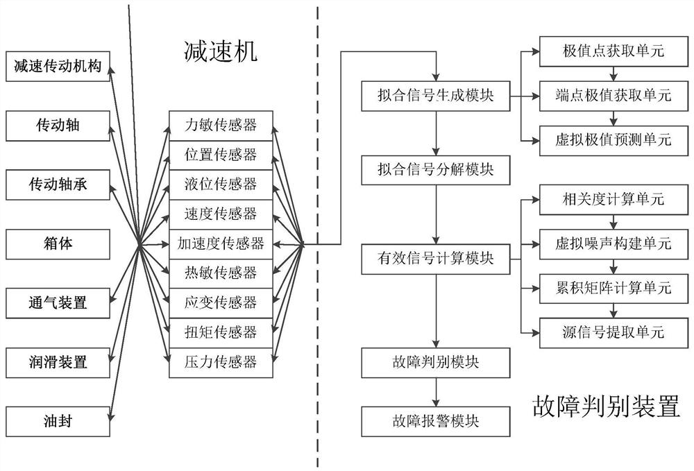
[0079] Refer below figure 1 The first embodiment of the reducer for automatically identifying faults disclosed in the present application will be described in detail. Such as figure 1 As shown, this embodiment mainly includes: a reduction transmission mechanism, a transmission shaft, a transmission bearing, a casing, a ventilation device, a lubricating device, an oil seal, an automatic fault discrimination device and a plurality of first sensors.

[0080] A plurality of first sensors are installed on at least one part of the reduction transmission mechanism, transmission shaft, transmission bearing, box body, ventilation device, lubricating device, and oil seal, and are used to detect and upload sensing sig...


PUM


Abstract

The invention discloses a speed reducer capable of automatically judging faults, and the speed reducer is characterized in that a plurality of first sensors are installed on at least one of a speed reduction transmission mechanism, a transmission shaft, a transmission bearing, a box body, a ventilation device, a lubricating device and an oil seal, and are used for detecting and uploading sensing signals of corresponding parts of the speed reducer. The speed reducer is additionally provided with a fault automatic judgment function, in the process from sensing signal collection to fault information determination, fluctuation of the end of a signal is avoided through fitting and decomposition, more accurate input is provided for signal decomposition, virtual noise is constructed through irrelevant signal components obtained after signal decomposition, and the speed reducer has the advantages of being simple in structure, convenient to use and high in practicability. Therefore, the extracted effective signals are more real, the noise reduction effect is better, and automatic fault judgment of the speed reducer and the elevator is achieved.

Description

technical field [0001] The present application relates to the technical field of fault identification, in particular to a reducer for automatically identifying faults, a hoist for automatically identifying faults, and an automatic fault identifying method thereof. Background technique [0002] The failure rate of mechanical equipment during operation is a pain point in the operation of equipment. For this reason, the method used is to install corresponding sensors on the equipment to detect the operating parameters and external changes of the equipment, so as to judge whether the equipment fails. For example, for a reducer, it is possible to judge whether the equipment is faulty by detecting the vibration, temperature, pressure and other data of the equipment. [0003] Due to the large number of detection points of the equipment, sensors are usually arranged at each detection point for detection. Continue to take vibration detection as an example, because there may be more t...

Claims


Application Information

Patent Timeline
Patent Type & Authority Applications(China)
IPC IPC(8): G08C25/00G01H17/00G01D21/02G07C3/00
CPCG01D21/02G01H17/00G07C3/00G08C25/00
Inventor 胡军金新华邹毅婷叶林胡开石
Owner JIANGSU GUOMAO REDUCER GRP CO LTD
Why Eureka
Try Eureka