High-voltage cable stripping device
A high-voltage cable and belt technology, applied in circuits, electrical components, electronic waste recycling, etc., can solve the problems of incompetent transmission efficiency of peeling mode, and achieve the effect of improving peeling efficiency and good peeling effect.
- Summary
- Abstract
- Description
- Claims
- Application Information
AI Technical Summary
Problems solved by technology
Method used
Image

Examples
Embodiment Construction
[0046] The following will clearly and completely describe the technical solutions in the embodiments of the present invention with reference to the accompanying drawings in the embodiments of the present invention. Obviously, the described embodiments are only some, not all, embodiments of the present invention. Based on the embodiments of the present invention, all other embodiments obtained by persons of ordinary skill in the art without making creative efforts belong to the protection scope of the present invention.
[0047] The object of the present invention is to provide a high-efficiency high-voltage cable stripping device for stripping high-strength cables.
[0048] In order to make the above objects, features and advantages of the present invention more comprehensible, the present invention will be further described in detail below in conjunction with the accompanying drawings and specific embodiments.
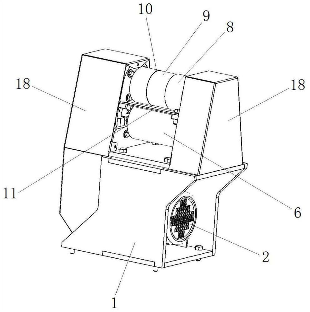
[0049] figure 1 It is the overall structural diagram of the hig...
PUM
 Abstract
Description
Claims
Application Information