
Axial rotor of axial gap type rotating motor

A technology of rotating electrical machines and axial gaps, applied in the field of rotors, can solve problems such as rotor magnets flying off, and achieve the effect of increasing reluctance torque

Inactive Publication Date: 2020-12-04
ADATA
View PDF2 Cites 0 Cited by
  • Summary
  • Abstract
  • Description
  • Claims
  • Application Information

AI Technical Summary

Problems solved by technology

[0003] However, there is still room for improvement in the arrangement of the rotor magnets in the patented patent No. TW I562509, and multiple rotor magnets will also be thrown off when the rotor rotates at a high speed due to the parallel arrangement.

Method used


Image

  • Axial rotor of axial gap type rotating motor
  • Axial rotor of axial gap type rotating motor
  • Axial rotor of axial gap type rotating motor

Examples


Embodiment

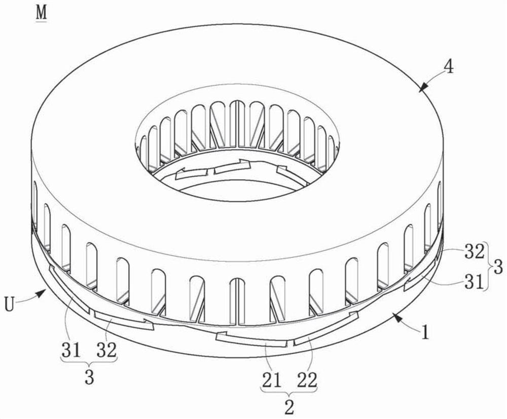
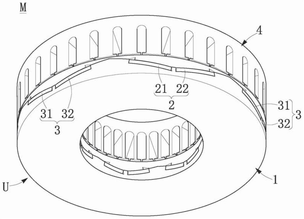
[0033] First, see figure 1 and figure 2 as shown, figure 1 and figure 2 They are three-dimensional schematic diagrams of axial gap rotating electrical machines according to embodiments of the present invention. The present invention provides an axial rotor U of an axial gap type rotating electrical machine M, that is, a rotor structure applicable to an axial electric motor. The axial gap type rotating electrical machine M may include a central shaft (not shown in the figure), at least one axial stator 4 and at least one axial rotor U. The axial rotor U can be arranged corresponding to the axial stator 4 so that the axial rotor U can rotate relative to the axial stator 4 .

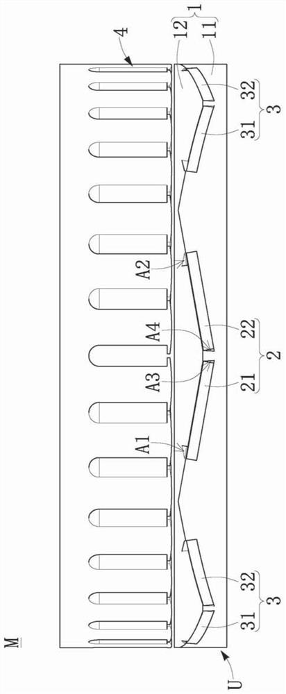
[0034] Based on the above, further speaking, the axial rotor U may include: an annular disk structure 1 and a plurality of magnetic element groups. A plurality of magnetic element groups can be disposed on the annular disk structure 1 , and the plurality of magnetic element groups surround a central ...


PUM


Abstract

The invention discloses an axial rotor of an axial gap type rotating motor. The axial rotor comprises an annular disc body structure and a plurality of magnetic element groups, wherein the plurality of magnetic element groups are arranged on the annular disc body structure, surround the central axis of the annular disc body structure and are arranged at intervals, each magnetic element group comprises a first magnetic element and a second magnetic element adjacent to the first magnetic element, and a preset included angle ranging from 5 degrees to 175 degrees is formed between the first magnetic element and the second magnetic element. According to the invention, the effect of increasing the reluctance torque is achieved.

Description

technical field [0001] The invention relates to a rotor, in particular to an axial rotor of an axial gap type rotating electrical machine. Background technique [0002] Firstly, in the prior art, there are many different axial-flow gap-type rotating electrical machines, so as to be suitable for high torque and / or high power occasions. For example, in the "Axial Flow Gap Rotating Electric Machine and Its Manufacturing Method, and Flywheel Electric Storage Device" disclosed by the patent publication number TW I562509, a plurality of rotor magnets are arranged parallel to each other and attached to the rotor core. [0003] However, there is still room for improvement in the arrangement of the rotor magnets disclosed in the patent No. TW I562509, and a plurality of rotor magnets will also fly off when the rotor rotates at a high speed because they are arranged in parallel. [0004] Therefore, how to overcome the above-mentioned defects by improving the structural design has bec...

Claims


Application Information

Patent Timeline
IPC IPC(8): H02K1/27
CPCH02K1/2793H02K2201/03H02K2201/12
Inventor 萧家祥林继谦阎柏均姚成福
Owner ADATA
Learn More