Steel bar cutting device for constructional engineering construction

A technology for steel bar cutting and construction engineering, applied in cleaning methods and tools, smoke and dust removal, chemical instruments and methods, etc., can solve problems such as the inability to achieve automatic and stable equal-distance cutting of steel bars, and achieve soil agitation. The effect of improving governance efficiency

Inactive Publication Date: 2020-12-08
王光远
View PDF1 Cites 7 Cited by
  • Summary
  • Abstract
  • Description
  • Claims
  • Application Information

AI Technical Summary

Problems solved by technology

Although the device can be used to cut steel bars, it cannot achieve automatic and stable equal-distance cutting of steel bars during the operation process. Therefore, a steel bar cutting device for construction engineering is now provided to solve the above technical problems

Method used


Image

  • Steel bar cutting device for constructional engineering construction
  • Steel bar cutting device for constructional engineering construction
  • Steel bar cutting device for constructional engineering construction

Examples


Embodiment 1

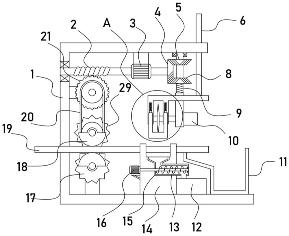
[0021] see Figure 1-3 , a kind of steel bar cutting device for building construction, comprising a fixed frame 1, a support frame 14 for supporting a steel bar 19 is fixed on the fixed frame 1, a biaxial motor 3 is fixed on the fixed frame 1, and one of the biaxial motors 3 The output shaft is driven and connected with a rotating mechanism, and the rotating mechanism is driven and connected with a translation mechanism for driving the lateral movement of the steel bar 19. The other output shaft of the biaxial motor 3 is driven and connected with a positive and negative mechanism. The mechanism drives and connects the limit frame 7, the limit frame 7 is fixed with a cutting motor 10, the output shaft of the cutting motor 10 is driven and connected with a cutting blade 24, the fixed frame 1 is fixed with a collecting box 12, and the collecting box 12 passes through the conveying mechanism It is connected with the support frame 14, and the right side of the support frame 14 is p...

Embodiment 2

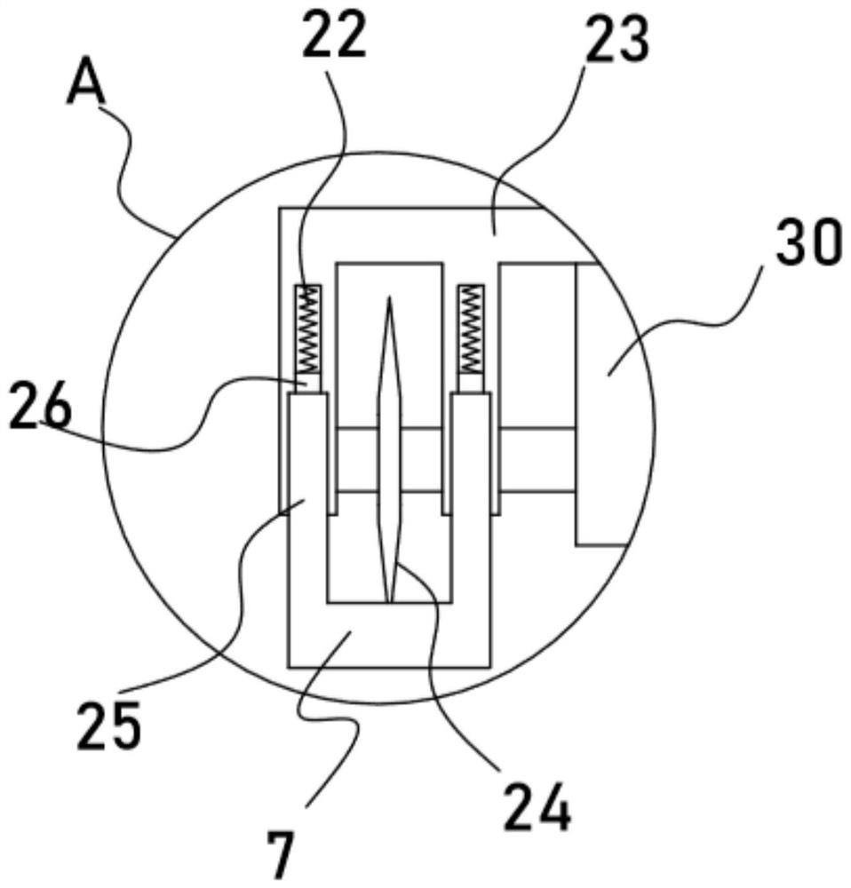
[0026] On the basis of Embodiment 1, in addition, the reversing mechanism provided in this device includes the incomplete bevel gear 4 driven to rotate, and the incomplete bevel gear 4 is alternately meshed with coaxially fixed bevel gear 15 and bevel gear II8. The lifting mechanism includes a threaded rod 9 coaxially fixed with the bevel gear II8, a threaded sleeve 30 is threaded on the threaded rod 9, and a lifting frame 23 is fixedly installed on the threaded sleeve 30 .

[0027] The double-axis motor 3 drives the worm 2 to rotate while driving the incomplete bevel gear 4 to rotate. During the rotation of the incomplete bevel gear 4, the incomplete bevel gear 4 alternately meshes with the bevel gear I5 and the bevel gear II8, thereby realizing the alternate clockwise rotation of the threaded rod 9 At this time, the threaded sleeve 30 drives the lifting frame 23 to reciprocate vertically, so that the rotating cutting blade 24 can cut the reinforcing bar 19 . The incomplete ...


PUM


Abstract

The invention discloses a steel bar cutting device for building engineering construction, and relates to the technical field of building construction. The steel bar cutting device comprises a fixing frame. A supporting frame used for supporting steel bars is fixed to the fixing frame. A cutting motor is fixed to a limiting frame. An output shaft of the cutting motor is in driving connection with acutting blade. A material collecting box is fixed to the fixing frame. The material collecting box is connected with the supporting frame through a conveying mechanism. A collecting groove used for collecting steel bars is formed in the right side of the supporting frame. According to the steel bar cutting device for the building engineering construction, a moving mechanism can transversely reciprocate through the arranged driving mechanism, at the moment, a concentric-square-shaped frame drives a mounting frame to achieve the rotating effect, that is, a stirring frame, used for stirring soil, on the mounting frame achieves reciprocating swing, and the soil stirring sufficient degree is remarkably improved. The arranged stirring frame can achieve the reciprocating swing effect, meanwhile,rotation can be achieved, soil in a storage tank is fully stirred and further improved, the soil and a medicament for treating the soil are fully contacted and mixed, and the soil treatment efficiency is greatly improved.

Description

technical field [0001] The invention relates to the technical field of building construction, in particular to a steel bar cutting device for building engineering construction. Background technique [0002] Building construction refers to the production activities in the implementation stage of engineering construction. It is the construction process of various buildings. It can also be said to be the process of turning various lines on the design drawings into real objects at designated locations. It includes basic engineering construction, main structure construction, roofing engineering construction, decoration engineering construction, etc. The place where the construction works is called "construction site" or "construction site", also called construction site. During the construction process, the steel bars need to be cut to the required length. [0003] The authorized notification number is that the patent of CN207982174 U discloses a steel bar cutting device, which...

Claims


Application Information

Patent Timeline
Patent Type & Authority Applications(China)
IPC IPC(8): B21F11/00B21F23/00B08B15/04
CPCB08B15/04B21F11/00B21F23/00
Inventor 王光远
Owner 王光远
Why Eureka
Try Eureka