Industrial screwdriver assembling equipment

A technology for assembling equipment and screwdrivers, used in metal processing equipment, metal processing, manufacturing tools, etc., can solve the problems of low efficiency, time-consuming and laborious, and achieve the effect of easy collection

Inactive Publication Date: 2020-12-08
潘富强
View PDF6 Cites 3 Cited by
  • Summary
  • Abstract
  • Description
  • Claims
  • Application Information

AI Technical Summary

Problems solved by technology

[0005] In order to overcome the shortcomings of time-consuming, labor-intensive and low-efficiency assembly of screwdrivers in existing equipment, the technical problem to be solved is to provide an industrial screwdriver assembly equipment that can realize continuous transmission of handles and knife rods, and can realize the collection of screwdrivers

Method used


Image

  • Industrial screwdriver assembling equipment
  • Industrial screwdriver assembling equipment
  • Industrial screwdriver assembling equipment

Examples


Embodiment 1

[0073] An industrial screwdriver assembly equipment such as figure 1 As shown, it includes a base 1, an electric push rod 2, a mounting plate 3, a feeding mechanism 4, a mounting mechanism 5, and a feeding frame 6 in sequence. The left front side of the base 1 is provided with an electric push rod 2, and the left and right sides of the rear of the base 1 Both are connected with a mounting plate 3, a sequential blanking mechanism 4 is connected between the mounting plate 3, the electric push rod 2 and the base 1, and a mounting mechanism 5 is connected between the left middle part of the base 1 and the sequential blanking mechanism 4, and the middle part of the base 1 A blanking frame 6 is connected, and the blanking frame 6 is located below the parts of the blanking mechanism 4 in sequence.

[0074] When people need to assemble a screwdriver, they first place the handle in the sequential unloading mechanism 4, place the cutter bar on the parts of the mounting mechanism 5, cont...

Embodiment 2

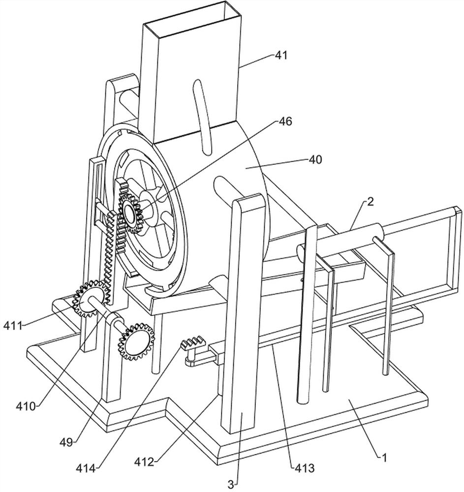
[0076] On the basis of Example 1, such as Figure 2-7 As shown, the blanking mechanism 4 includes a rotary sleeve 40, a blanking frame 41, a feeding tray 42, a clamping frame 43, a first spring 44, a first wedge block 45, a one-way gear 46, a chute plate 47, Two-way rack 48, mounting seat 49, rotating shaft 410, second gear 411, first sliding sleeve 412, slide bar 413 and short rack 414, the inner side of mounting plate 3 is connected with rotating sleeve 40, and the top of rotating sleeve 40 is connected There is a blanking frame 41, a feed tray 42 is rotatably connected to the inside of the rotary sleeve 40, a one-way gear 46 is connected to the rear side of the middle part of the feed tray 42, and a clamping frame 43 is evenly slidably connected to the periphery of the feeding tray 42, and the clamping frame The first spring 44 is connected between the inner side of 43 and the feeding tray 42, and the first spring 44 is set on the outside of the clamping frame 43. The left ...

Embodiment 3

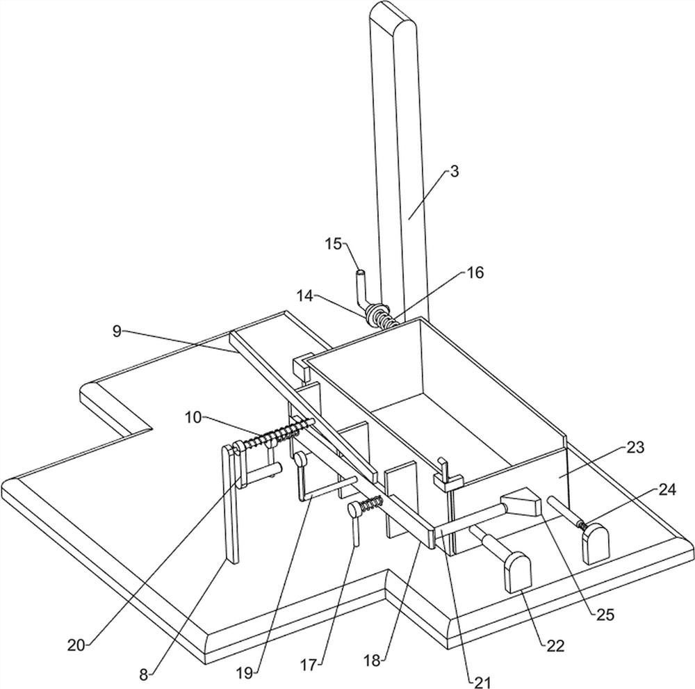
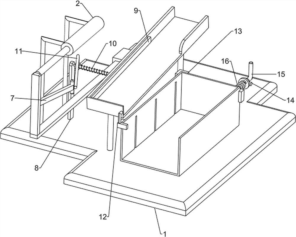
[0081] On the basis of Example 2, such as Figure 8-9 As shown, it also includes a push rod 7, a guide rod 8, a push frame 9, a second spring 10, an oblique rod 11, a first limit block 12, a second limit block 13, a third sliding sleeve 14, and a clamping block 15 and the third spring 16, the push rod 7 is connected to the middle part of the slide rod 413, the guide rod 8 is connected to the left front part of the base 1, the guide rod 8 is located directly below the electric push rod 2, and the right side of the upper part of the guide rod 8 passes through the blanking Frame 6, the upper part of the guide rod 8 is slidably connected with an oblique rod 11, the lower part of the oblique rod 11 is set on the outside of the guide rod 8, and the second spring 10 is connected between the left side of the oblique rod 11 and the blanking frame 6, and there are 10 sets of second springs On the outside of the inclined bar 11, the right side of the inclined bar 11 passes through the bl...


PUM


Abstract

The invention relates to assembling equipment, in particular to industrial screwdriver assembling equipment. The industrial screwdriver assembling equipment can continuously convey handles and cutterbars and can collect screwdrivers. The industrial screwdriver assembling equipment comprises a base, an electric push rod, mounting plates, a sequential discharging mechanism, a mounting mechanism anda discharging frame, wherein the electric push rod is arranged on one side of the base; the mounting plates are connected to the two sides of the base; the sequential discharging mechanism is connected among the mounting plates, the electric push rod and the base; the mounting mechanism is connected between the base and the sequential discharging mechanism; and the discharging frame is connectedto the middle of the base and located on the side of a component of the sequential discharging mechanism. Through the cooperation of the electric push rod, the sequential discharging mechanism and themounting mechanism, the electric push rod moves to enable the cutter bars of the mounting mechanism to complete the discharging, meanwhile, the sequential discharging mechanism can continuously rotate and feed the handles, and thus people can assemble the cutter bars conveniently.

Description

technical field [0001] The invention relates to an assembly device, in particular to an industrial screwdriver assembly device. Background technique [0002] A screwdriver is a common tool used to turn a screw to make it in place. It usually has a thin wedge-shaped head that can be inserted into the slot or notch of the screw head. Screwdrivers are divided into flat and cross. In daily life, people A screwdriver will be used, and the screwdriver shaft can be used by people to assemble and disassemble parts. To make a screwdriver, the knife shaft and the handle need to be assembled. [0003] Patent application CN201810242933.X is a screwdriver assembly device. When working, the rotating motor drives the driving wheel to rotate. The driving wheel drives the synchronous wheel to rotate through the transmission belt. The connected handle support frame and the tool bar support frame rotate synchronously, the tool bar falls from the feeding mechanism into the tool bar accommodati...

Claims


Application Information

Patent Timeline
Patent Type & Authority Applications(China)
IPC IPC(8): B23P19/00
CPCB23P19/00B23P19/001
Inventor 潘富强
Owner 潘富强
Why Eureka
Try Eureka