
Screw limiting mechanism, screw feeding mechanism, screw screwing machine and screw locking method

A technology of limiting mechanism and feeding mechanism, applied in metal processing, metal processing equipment, manufacturing tools, etc., can solve the problem of reducing the positioning accuracy of the clamping jaw on the screw, the head end of the screw is difficult to ensure that the head end is downward, and it cannot be effectively grasped. and other problems, to achieve the effect of easy processing, improving service life, and reducing the difficulty of positioning

Pending Publication Date: 2020-12-08
JIANGSU XINTIMU INTELLIGENT EQUIP CO LTD
View PDF2 Cites 1 Cited by
  • Summary
  • Abstract
  • Description
  • Claims
  • Application Information

AI Technical Summary

Problems solved by technology

[0006] However, for some small-sized screws, such as screws with specifications below M3 and / or with relatively small length and diameter, due to the small size of the screw, when the screw falls obliquely from the inclined channel into the longitudinal channel, the height difference and the larger The diameter of the large feeding channel makes the screw have sufficient turning space, so it is difficult to ensure that the head end of the screw is facing down and the tail end is facing up, which causes the subsequent screwdriver to absorb the screw and lock it by vacuum suction. , which greatly affects the reliability of screw locking
[0007] At the same time, when working, the jaws need to be opened and closed repeatedly under the force of the bit head, and there is continuous friction loss between the bit head and the jaws. After long-term use, the jaws will also be deformed due to wear, and the jaws will be deformed after deformation. As a result, the matching accuracy of multiple jaws is reduced, and the positioning accuracy of the jaws to the screw is reduced, resulting in the inability to effectively grasp

Method used


Image

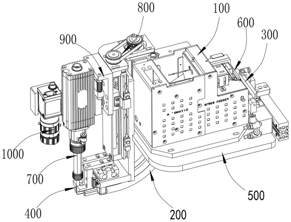
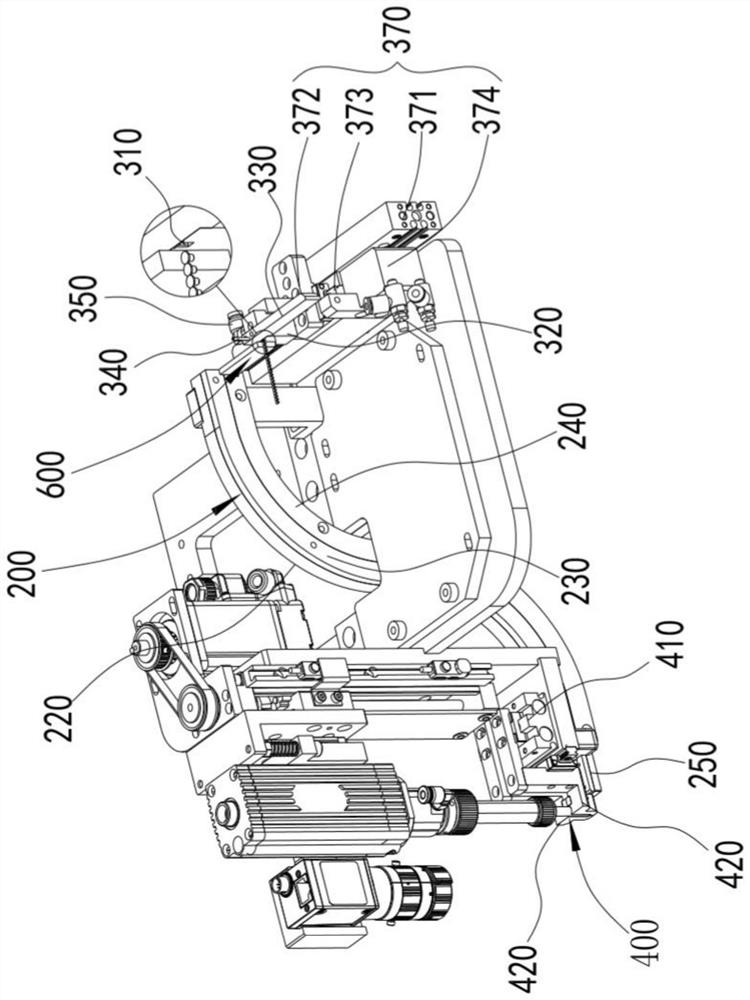
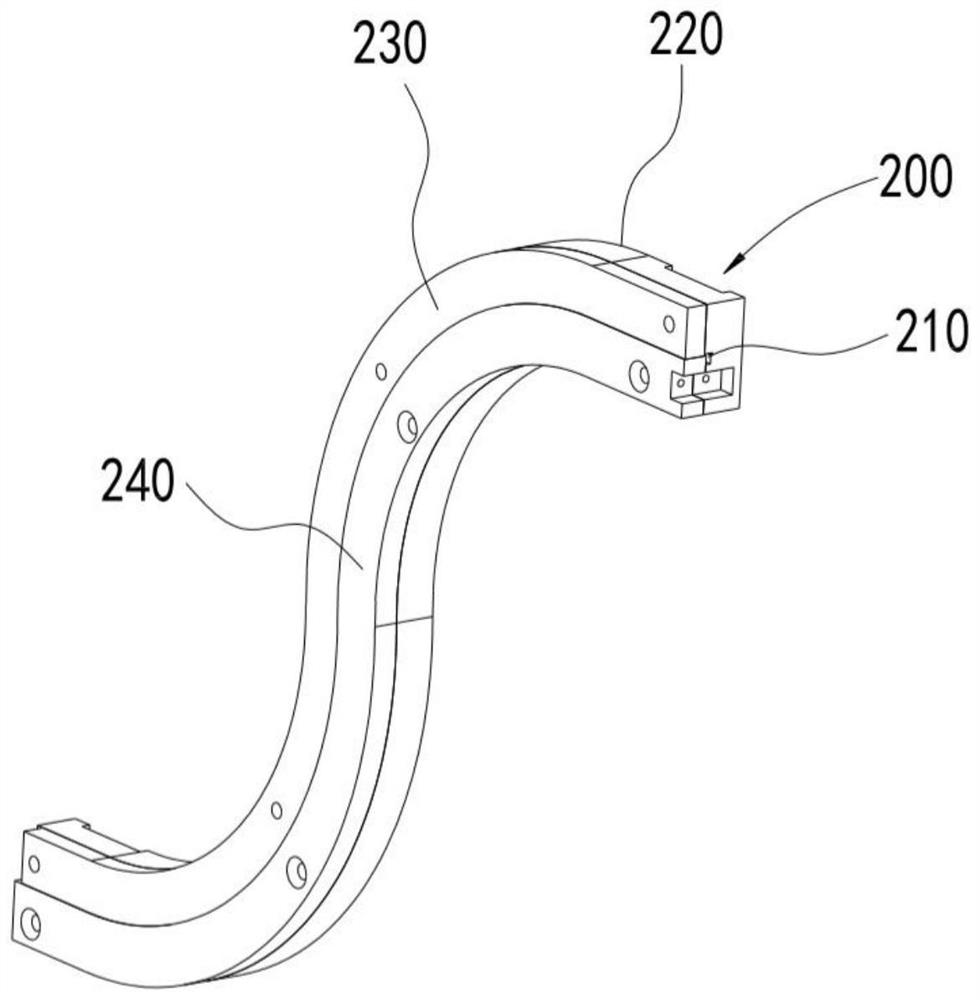
  • Screw limiting mechanism, screw feeding mechanism, screw screwing machine and screw locking method
  • Screw limiting mechanism, screw feeding mechanism, screw screwing machine and screw locking method
  • Screw limiting mechanism, screw feeding mechanism, screw screwing machine and screw locking method

Examples


Embodiment Construction

[0070] Objects, advantages and features of the present invention will be illustrated and explained by the following non-limiting description of preferred embodiments. These embodiments are only typical examples of applying the technical solutions of the present invention, and all technical solutions formed by adopting equivalent replacements or equivalent transformations fall within the protection scope of the present invention.

[0071] In the description of the scheme, it should be noted that the terms "center", "upper", "lower", "left", "right", "front", "rear", "vertical", "horizontal", " The orientation or positional relationship indicated by "inner", "outer", etc. is based on the orientation or positional relationship shown in the drawings, and is only for the convenience of description and simplification of description, rather than indicating or implying that the device or element referred to must have a specific orientation , constructed and operated in a particular or...


PUM


Abstract

The invention discloses a screw limiting mechanism, a screw feeding mechanism, a screw screwing machine and a screw locking method. The screw limiting mechanism comprises a screw positioning channel with one exposed end and a material taking channel communicating with the screw positioning channel, the cross section of the screw positioning channel is T-shaped, and the material taking channel is located above the transverse part of the screw positioning channel. The extending direction of the material taking channel is perpendicular to the extending direction of the screw positioning channel.According to the scheme, the T-shaped screw positioning channel is adopted in the screw limiting mechanism, meanwhile, the extending direction of the material taking channel is perpendicular to that of the screw positioning channel, screws only move in the positioning channel when entering the material taking position, and a T-shaped channel structure can avoid the problem that the screws are notturned over in the conveying process; and the state that heads of the screws right facing the material taking channel face downwards and the tails of the screws face upwards is effectively guaranteed,the feeding precision is improved, and meanwhile, feeding of the screws of various specifications is suited.

Description

technical field [0001] The invention relates to the field of screw machines, in particular to a screw limiting mechanism, a screw feeding mechanism, a screw screwing machine and a screw locking method. Background technique [0002] The screw machine is a small machine that automatically locks screws. Its action structure can generally be divided into two parts: the feeding part and the electric batch part. The feeding part is responsible for screening and providing screws, and the electric batch part is responsible for taking screws and locking screws. The generation of the machine not only improves the working efficiency but also reduces the intensity of manual work. [0003] The feeding part is the core part of the screw machine, the stability and accuracy of its feeding directly affects the realization of subsequent batch picking and locking. [0004] In various air blowing feeding structures, the screws blown through the air pipe are usually received and limited by scre...

Claims


Application Information

Patent Timeline
IPC IPC(8): B23P19/06B23P19/00
CPCB23P19/001B23P19/06
Inventor 季荣叶际勃刘深龙谭敏章赟孙凯杨志勇范锦宇孙淮扬卢赛赛钱浩东周立静李风武
Owner JIANGSU XINTIMU INTELLIGENT EQUIP CO LTD
Learn More