Textile machine with air flow conveyor and filter device

A filtering device and air conveying technology, applied in the textile field, can solve the problems affecting the integrity of the fabric and the defects of the textile fabric, and achieve the effect of reducing the defects and improving the integrity.

Pending Publication Date: 2020-12-08
成都魔视网络科技有限公司
View PDF6 Cites 0 Cited by
  • Summary
  • Abstract
  • Description
  • Claims
  • Application Information

AI Technical Summary

Problems solved by technology

[0002] The textile machine is a device used to process silk, cotton thread, hemp or fiber into cloth. Since different materials have different degrees of floating flocs, it is easy to cause blockage inside the textile machine. The air flow in the textile machine is transported so that it enters the filter from the air intake pipe to filter the air inside the textile machine, preventing the silk yarns generated during the textile process from flying out and causing blockage inside the textile machine. When silk thread is woven, due to the fiber structure characteristics of wool and its strong tensile resistance, the silk thread is not easy to fall off when it is entangled on the spindle during the weaving process, and cannot follow the airflow sent by the airflow conveyor into the filter device, resulting in textile fabrics Flaws appear that affect the integrity of the fabric

Method used


Image

  • Textile machine with air flow conveyor and filter device
  • Textile machine with air flow conveyor and filter device
  • Textile machine with air flow conveyor and filter device

Examples


Embodiment 1

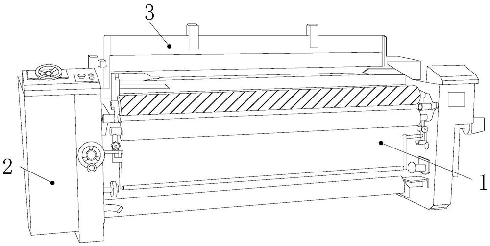
[0024] as attached figure 1 to attach Figure 4 Shown:

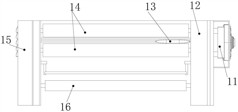
[0025] The invention provides a textile machine with an airflow conveyor and a filter device, the structure of which comprises a textile rack 1, a cover 2, and a thread frame 3, the outer side of the left end of the textile frame 1 is riveted to the outer cover 2, and the thread frame 3 is connected to the outer cover 2 by riveting. The upper side of the textile frame 1 is embedded and connected. The textile frame 1 includes a fan 11, a transmission box 12, a spindle 13, a distribution roller 14, a filter box 15, and a collection roller 16. The fan 11 is welded to the right side of the transmission box 12. The transmission box 12 is axially connected to the right side of the distribution roller 14, the spindle 13 is movably engaged between the transmission box 12 and the filter box 15, the filter box 15 is axially connected to the left side of the distribution roller 14, and the collection roller 16 is connected betwee...

Embodiment 2

[0031] as attached Figure 5 to attach Figure 7 Shown:

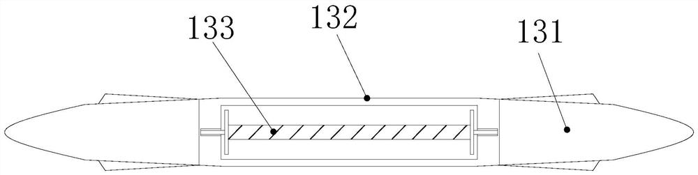
[0032] Wherein, the cutting head 31b includes an arc-shaped plate b1, a fixed block b2, a dust shield b3, a spring plate b4, and a cutting wall b5. The arc-shaped plate b1 is attached to the lower side of the cutting wall b5, and the fixed block b2 is welded to the upper right side of the arc-shaped plate b1, the dust shield b3 is welded to the upper right side of the fixed block b2, and the elastic plate b4 is connected between the inner side of the middle part of the dust shield b3 and the left end of the fixed block b2 , the left end of the cutting wall b5 is axially connected to the left end of the conical cover 31a, and the spring plate b4 is made of carbon spring steel, which has the characteristics of good elasticity and fatigue resistance, so that the dust shield b3 can reset itself, and there is It is beneficial to reduce the clogging of the cutting head 31b by floating flocs caused by thin wires.

[0033] W...


PUM


Abstract

The invention discloses a textile machine with an air flow conveyor and a filter device. The textile machine structurally comprises a textile frame, an outer cover and a thread stand, wherein the outer side of the left end of the textile frame is connected with the outer cover in a riveted mode, the thread stand is fixedly connected with the upper side of the thread stand in an embedded mode, thetextile frame comprises a draught fan, a transmission box, a spindle, distribution rollers, a filtering box and a collecting roller, the draught fan is connected to the right side of the transmissionbox in a welded mode, and the transmission box is connected with right side shafts of the distribution rollers. In the shuttle flying process, a conical cover can feed silk floated wadding into a cutting head, the cutting head pulls a spring open under pushing of a movable rod along kinetic potential to be pushed away through a sliding rod so as to cut the silk floated wadding, silk threads are prevented from winding the interior of the textile machine, the integrity of woven fabric is improved, a buffer pad can drive a cutting edge to be folded around a middle shaft, so that the silk threadsare sheared off by a shear opening on the inner side of the shear opening, the silk threads are prevented from being wound around the surface of the spindle, and fabric surface defects are reduced.

Description

technical field [0001] The invention belongs to the textile field, and more specifically relates to a textile machine with an air conveyor and a filtering device. Background technique [0002] The textile machine is a device used to process silk, cotton thread, hemp or fiber into cloth. Since different materials have different degrees of floating flocs, it is easy to cause blockage inside the textile machine. The air flow in the textile machine is transported so that it enters the filter from the air intake pipe to filter the air inside the textile machine, preventing the silk yarns generated during the textile process from flying out and causing blockage inside the textile machine. When silk thread is woven, due to the fiber structure characteristics of wool and its strong tensile resistance, the silk thread is not easy to fall off when it is entangled on the spindle during the weaving process, and cannot follow the airflow sent by the airflow conveyor into the filter devic...

Claims


Application Information

Patent Timeline
IPC IPC(8): D03J1/00B01D46/00
CPCB01D46/00D03J1/002
Inventor 黄小炜
Owner 成都魔视网络科技有限公司
Why Eureka
Try Eureka