Radar system comprising two back-to-back positioned radar antenna modules, and radar system holding antenna module with cavity slotted-waveguide antenna arrays for radiating and receving radar wave signals

A technology of antenna module and antenna array, applied in the field of radar system

Pending Publication Date: 2020-12-08
罗宾雷达设备有限公司
View PDF0 Cites 3 Cited by
  • Summary
  • Abstract
  • Description
  • Claims
  • Application Information

AI Technical Summary

Problems solved by technology

Noise can be introduced by allowing false reflections f

Method used


Image

  • Radar system comprising two back-to-back positioned radar antenna modules, and radar system holding antenna module with cavity slotted-waveguide antenna arrays for radiating and receving radar wave signals
  • Radar system comprising two back-to-back positioned radar antenna modules, and radar system holding antenna module with cavity slotted-waveguide antenna arrays for radiating and receving radar wave signals
  • Radar system comprising two back-to-back positioned radar antenna modules, and radar system holding antenna module with cavity slotted-waveguide antenna arrays for radiating and receving radar wave signals

Examples


Embodiment Construction

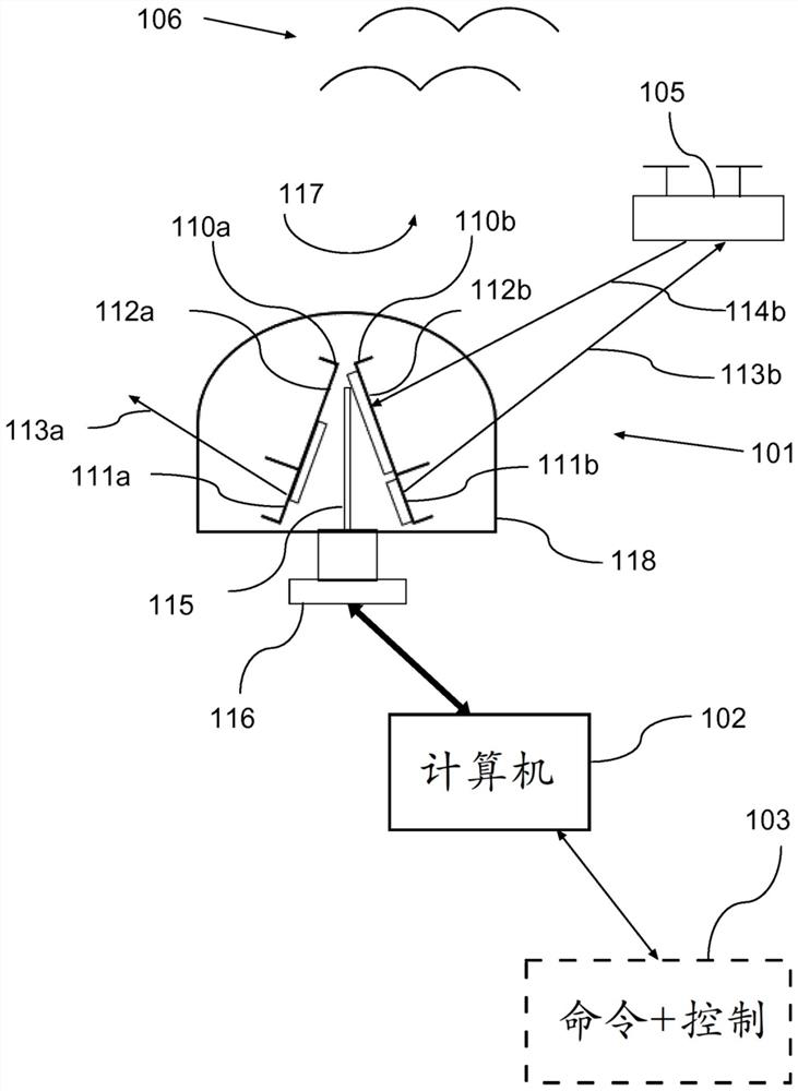
[0174] Figure 1a is a schematic block diagram illustrating the basic configuration of the scanning radar system according to the first exemplary embodiment. The system includes a rotary scanning radar system 101 configured to operate as a frequency modulated continuous wave (FMCW) radar system. Scanning radar system 101 is electrically connected to computer system 102 . The generated output data may be communicated to the external command and control system 103, where the data may be communicated by real-time data streaming, where for example Extensible Markup Language XML may be used for streaming.

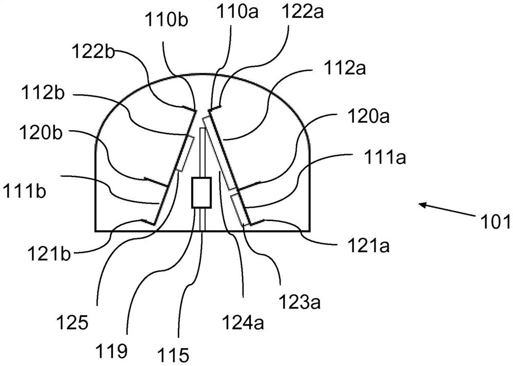
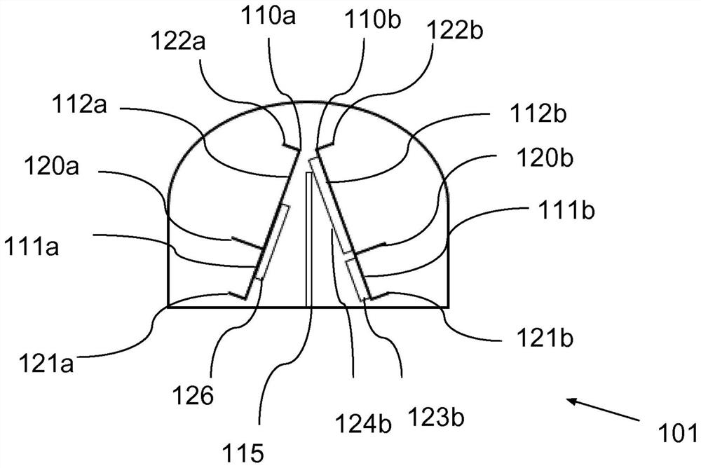
[0175] The scanning radar system 101 accommodates two antenna modules positioned back-to-back, namely a first antenna module 110a and a second antenna module 110b, wherein each antenna module 110a, 110b includes a first planar slot configured to radiate electromagnetic waves 113a, 113b A waveguide antenna array 111a, 111b and a second planar slotted waveguide antenna array 112a...


PUM

PropertyMeasurementUnit
Thicknessaaaaaaaaaa

Abstract

There is provided a radar system comprising a first and a second antenna module, where each of the antenna modules comprises a first planar slotted waveguide antenna array configured for radiating electromagnetic waves, and a second planar slotted waveguide antenna array configured for receiving electromagnetic waves. The radar system further comprises a rotation system configured for supporting and rotating the first and second antenna modules around a vertical axis, with the first and second antenna modules arranged in a back-to-back position on opposite sides of a plane intersecting the vertical axis of rotation. There is also provided another radar system comprising a first radar antenna module, which radar module comprises a first planar slotted waveguide antenna array configured forradiating electromagnetic waves, and a second planar slotted waveguide antenna array configured for receiving electromagnetic waves, where each of the planar slotted waveguide antenna arrays comprisesseveral longitudinal extending waveguide columns, where the waveguide columns have a front side and a rear side with a plurality of cavity slots on the front side. The front side of the columns holding the cavity slots of the first planar antenna array are positioned in a first plane and the front side of the columns holding the cavity slots of the second planar antenna array are positioned in asecond plane parallel to the first plane, where the first and second antenna arrays may be positioned at a distance to each other in a direction to the first and second planes. The first and second parallel planes may also or alternatively be offset with a minimum perpendicular array distance to each other in a direction perpendicular to the planes.

Description

technical field [0001] The present disclosure relates to a radar system comprising two radar antenna modules positioned back-to-back. The present disclosure also relates to a radar system housing a cavity slotted waveguide antenna array for radiating and receiving radar wave signals. The present disclosure also relates to an antenna module having a radiating antenna array and a receiving antenna array positioned at a distance from each other. Background technique [0002] Slotted waveguide antennas SWA are well known in the prior art, where the waveguides may be arranged as an array of waveguides, such as a planar array of parallel waveguides. As the name implies, a slotted waveguide antenna consists of a waveguide of various lengths with multiple slots formed in the conducting walls of the waveguide. These slots introduce a discontinuity in the conductor and interrupt the flow of current along the waveguide. Instead, the current must flow around the edges of the slots, c...

Claims


Application Information

Patent Timeline
IPC IPC(8): H01Q3/04H01Q21/00H01Q25/00G01S13/34G01S13/42G01S13/88H01Q1/52
CPCG01S13/34G01S13/426G01S13/88G01S7/027H01Q1/525H01Q3/04H01Q21/005H01Q25/005G01S7/02
Inventor 希特·汉明格罗伯·范德梅尔
Owner 罗宾雷达设备有限公司
Why Eureka
Try Eureka