Forage processing device for animal husbandry
A treatment device, a technology of animal husbandry, applied in the direction of mixers with rotating stirring devices, agriculture, transportation and packaging, etc., can solve the problems of uneven mixing, long time, no ability to adjust cutting grass, etc.
- Summary
- Abstract
- Description
- Claims
- Application Information
AI Technical Summary
Problems solved by technology
Method used
Image
Examples
specific Embodiment approach 1
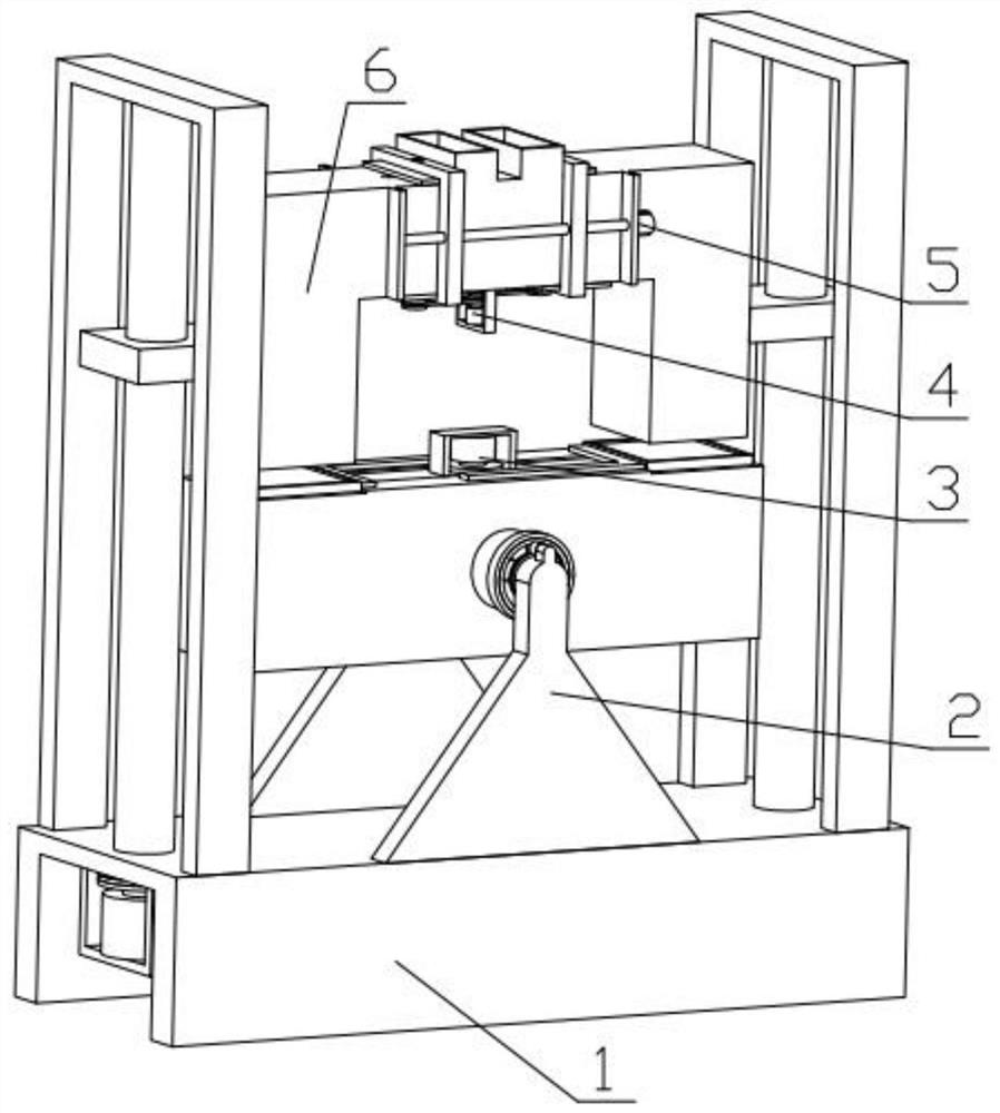
[0032] Combine below Figure 1-13 Describe this embodiment, a livestock forage processing device, including a docking mechanism 1, a rolling stirring mechanism 2, a sealing mechanism 3, a material cutting mechanism 4, an adjustment assembly 5 and a U-shaped housing 6, and the rolling stirring mechanism 2 is fixedly installed On the docking mechanism 1, the sealing mechanism 3 is fixedly installed on the rolling stirring mechanism 2, the material cutting mechanism 4 is fixedly installed on the U-shaped casing 6, the adjustment assembly 5 is fixedly installed on the U-shaped casing 6, and the U-shaped casing 6 and the docking mechanism 1 threaded connection, the material cutting mechanism 4 is connected with the adjustment assembly 5.
specific Embodiment approach 2
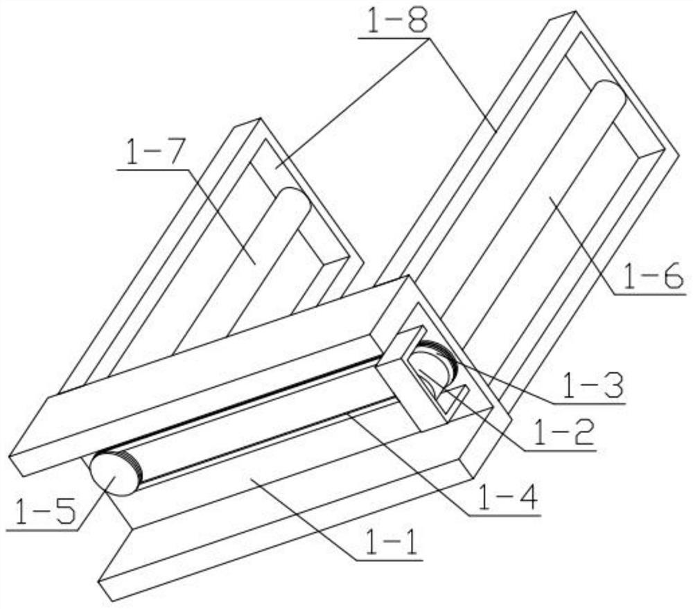
[0034] Combine below Figure 1-13 Describe this embodiment, this embodiment will further explain the first embodiment, the docking mechanism 1 includes a base frame 1-1, a bottom motor 1-2, a bottom sprocket 1-3, a bottom chain 1-4, a bottom Sprocket two 1-5, threaded column one 1-6, threaded column two 1-7, U-shaped support 1-8, the two ends of base frame seat 1-1 are fixedly installed with U-shaped support 1-8 respectively, a U-shaped Threaded column one 1-6 is installed in rotation on the U-shaped support 1-8, threaded column two 1-7 is installed in rotation on the other U-shaped support 1-8, and the other end of threaded column two 1-7 is fixedly installed with a bottom sprocket Two 1-5, the other end of threaded column one 1-6 is fixedly installed with bottom sprocket one 1-3, and bottom sprocket one 1-3 and bottom sprocket two 1-5 are all meshed with bottom chain 1-4, The output end of the bottom motor 1-2 is fixedly installed with a bottom sprocket 1-3, the bottom moto...
specific Embodiment approach 3
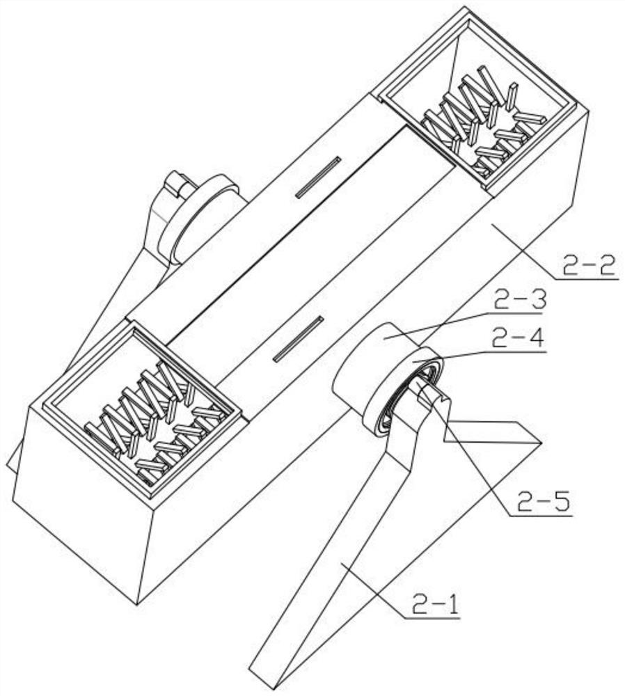
[0036] Combine below Figure 1-13 Describe this embodiment, this embodiment will further explain the second embodiment, the rolling stirring mechanism 2 includes a triangular leg 2-1, a rectangular material box 2-2, a side cylinder 2-3, a fixed ring 2-4, a rolling Motor 2-5, rolling gear 2-6, intermediate sprocket 2-7, limit lever 2-8, helical gear 2-9, helical gear ring 2-10, stirring shaft 2-11, triangular leg 2 -1 is fixedly installed on the base frame 1-1, the rolling motor 2-5 is fixedly installed on the triangle leg 2-1, the fixed ring 2-4 is fixedly installed on the triangle leg 2-1, and the side cylinder 2-3 rotates Installed on the fixed ring 2-4, the rolling gear 2-6 is fixedly installed on the output end of the rolling motor 2-5, the rolling gear 2-6 is meshed with the side cylinder 2-3, and the rolling gear 2-6 is in contact with the side cylinder 2-3. The intermediate sprocket 2-7 is meshed, and the intermediate sprocket 2-7 is rotatably installed in the groove p...
PUM
 Abstract
Description
Claims
Application Information
 - R&D
- Intellectual Property
- Life Sciences
- Materials
- Tech Scout
- Unparalleled Data Quality
- Higher Quality Content
- 60% Fewer Hallucinations
Browse by: Latest US Patents, China's latest patents, Technical Efficacy Thesaurus, Application Domain, Technology Topic, Popular Technical Reports.
© 2025 PatSnap. All rights reserved.Legal|Privacy policy|Modern Slavery Act Transparency Statement|Sitemap|About US| Contact US: help@patsnap.com


