
Deinsectization lamp system and deinsectization lamp

A technology of insect-killing lamps and indicator lights, which is applied to devices for catching or killing insects, electrical components, animal husbandry, etc. It can solve problems such as troublesome cleaning process, failure to attract insects, hidden dangers of power grid safety, etc., to avoid electric shock hazards, avoiding waste of electric energy, and preventing potential safety hazards

Inactive Publication Date: 2020-12-11
天台光润五金机电有限公司
View PDF6 Cites 0 Cited by
  • Summary
  • Abstract
  • Description
  • Claims
  • Application Information

AI Technical Summary

Problems solved by technology

In the prior art, there are special insect repelling devices to solve this problem, such as the use of insect trap lights, but in the existing technology, the most common insect trap lamps use sticky substances after attracting insects through lights. Sticking mosquitoes to kill insects, this method often requires manual cleaning, and the cleaning process is cumbersome and unhygienic
Another common method is to enclose a layer of electric grid around the insect trap lamp, and kill insects through electric current like an electric mosquito swatter. This technology liberates human hands, but in rainy days, continuous use of the electric grid has potential safety hazards. , and the use of insect traps during the day often has the effect that the light of the traps is not obvious and cannot attract insects; usually, when the environment does not allow, the traps and the power grid are manually turned off, although it can save electricity or It is to eliminate potential safety hazards, but during the closure period, the insects cannot be eliminated normally, which will bring a certain planting burden to the plantation

Method used


Image

  • Deinsectization lamp system and deinsectization lamp
  • Deinsectization lamp system and deinsectization lamp
  • Deinsectization lamp system and deinsectization lamp

Examples


Embodiment 1

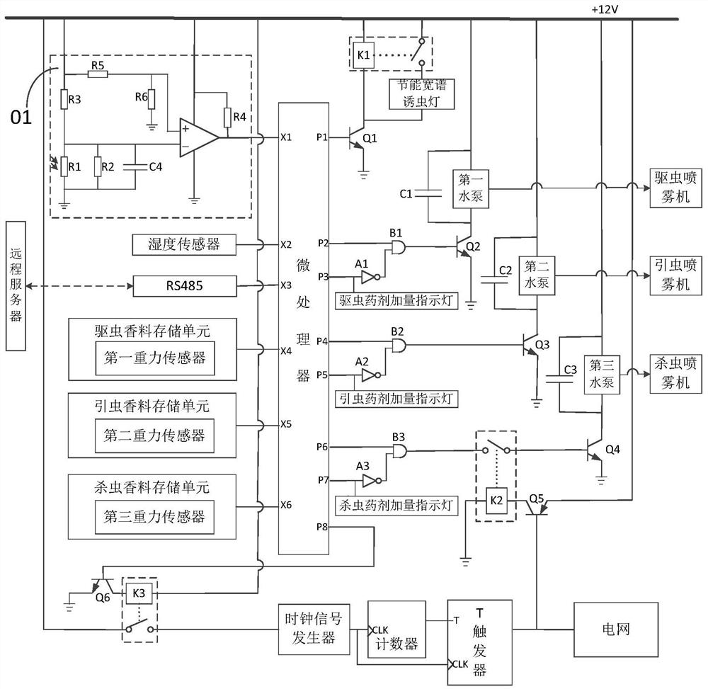
[0035] This embodiment discloses an insect killing lamp system, which is equipped with a photosensitive device and a humidity sensor. The insects are lured by the insect trap lamp 100 and the insect spraying spray, and the insects are killed by the power grid 200 and the insecticidal sprayer 800, which can realize Turn off the use of the lure light during the day and turn it on at night, and it can be realized that the power grid 200 is turned off and used on a rainy day and turned on at night.

[0036] A pest control lamp system disclosed in this embodiment includes a microprocessor, a light control circuit 01, a humidity sensor, an insect trap lamp 100 and a power grid 200, and the microprocessor includes multiple input terminals and multiple output terminals. Wherein, the light control circuit 01 is electrically connected to the first input terminal X1 of the microprocessor, and the light control circuit 01 is used to convert the sensed light signal into an electrical signal...

Embodiment 2

[0050] This embodiment discloses an insect-killing lamp, which adopts the insect-killing lamp system described in Embodiment 1, and attaches Image 6 It is a schematic diagram of the structure of this embodiment. This embodiment includes an energy-saving broad-spectrum insect trap lamp 100 and a power grid 200. The periphery of the insect-killing lamp is surrounded by a layer of power grid 200. When the energy-saving broad-spectrum insect trap lamp 100 is turned on, insects are lured into the power grid 200. At this time, the power grid 200 is in an open state, and therefore the insects are electrocuted. On the top of the energy-saving wide-capable insect trap lamp 100, an insect-inducing agent storage unit 400 and an insecticide storage unit 500 are also provided, and an insect-inducing sprayer 700 and an insecticidal sprayer 800 are provided, wherein the insect-inducing agent storage unit 400 , the insecticide storage unit 500, the insecticide sprayer 700 and the insecticide...

Embodiment 3

[0052] In this embodiment, on the basis of Embodiment 2, an insect repellent storage unit 300 and an insect repellent sprayer 600 are added (fixedly connected) to the top of the energy-saving Kuanpu insect trap lamp 100, and the insect repellant sprayer 600 and the insect repellant storage unit 300 connection, and obtain insect repellent from the insect repellent storage unit 300 for spraying; under the setting of the remote server, when plants need insects to spread pollen, but it is not suitable to gather too many insects, insect repellent can be carried out seasonally Treatment without complete extermination.


PUM


Abstract

The invention discloses a deinsectization lamp system which comprises a microprocessor, a light-operated circuit, a humidity sensor, a trap lamp, a power grid, a first relay and a third relay. The light-operated circuit is electrically connected with the first input end of the microprocessor, and the light-operated circuit converts sensed illumination signals into electric signals and inputs the electric signals to the microprocessor; the humidity sensor is electrically connected with the third input end of the microprocessor, and the humidity sensor converts a sensed humidity signal into an electric signal and inputs the electric signal to the microprocessor; the trap lamp is arranged at the first output end of the microprocessor, and a level signal output by the first output end controlsthe on / off state of a contact switch of the first relay so as to control the trap lamp to work; and the power grid is arranged at the eighth output end of the microprocessor, and a level signal output by the eighth output end controls the on / off state of a contact switch of the third relay so as to control the power grid to work. According to the deinsectization lamp system, the trap lamp can beturned off in the daytime and turned on at night, and the power grid can be turned on in sunny days and turned off in rainy days.

Description

technical field [0001] The invention belongs to the technical field of extermination of insects, in particular to an extermination lamp system and an extermination lamp. Background technique [0002] Because the plants planted in the Chinese herbal medicine plantation are Chinese herbal medicines, most of the Chinese herbal medicines are edible or have an aromatic smell, which are very easy to attract insects, such as the problems of mosquito harassment, various pests invading, eating, settling, and breeding. In the prior art, there are special insect repelling devices to solve this problem, such as the use of insect trap lights, but in the existing technology, the most common insect trap lamps use sticky substances after attracting insects through lights. Sticking mosquitoes to kill insects, this method often requires manual cleaning, and the cleaning process is cumbersome and unhygienic. Another common method is to enclose a layer of electric grid around the insect trap...

Claims


Application Information

Patent Timeline
Patent Type & Authority Applications(China)
IPC IPC(8): A01M1/04A01M1/22A01M1/20A01M7/00H05B47/11
CPCA01M1/04A01M1/20A01M1/223A01M7/0025A01M7/0089H05B47/11Y02B20/40
Inventor 夏法笳
Owner 天台光润五金机电有限公司
Learn More