Cervical vertebra treatment chair for medical care

A treatment chair and cervical spine technology, applied in the field of cervical spine treatment chairs, can solve problems such as the inability to quickly relieve cervical fatigue, and achieve the effect of improving the effect of nursing and relaxation

Pending Publication Date: 2020-12-11
HARBIN QUANKE MEDICAL TECH DEV
View PDF14 Cites 6 Cited by
  • Summary
  • Abstract
  • Description
  • Claims
  • Application Information

AI Technical Summary

Problems solved by technology

The arrangement of the right boom bar, the left boom bar, the hanging ring, the traction belt hook, the dynamometer and the buffer spring of the utility model is beneficial to the hooking and fixing of the cervical vertebra traction belt, and can test the pulling force and be able to The effect of shock absorption and buffering; the setting of longitudinal slide rails, moving sliders and jacking bolts is conducive to height adjustment, which is convenient for different patients to grasp; the setting of back support plate, back cushion and cushion cushion is conducive to the adjustment of The patient's body plays a supporting role and gives the patient good comfort; but the treatment chair cannot quickly relieve the user's cervical fatigue

Method used


Image

  • Cervical vertebra treatment chair for medical care
  • Cervical vertebra treatment chair for medical care
  • Cervical vertebra treatment chair for medical care

Examples


specific Embodiment approach 1

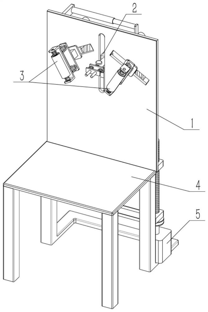
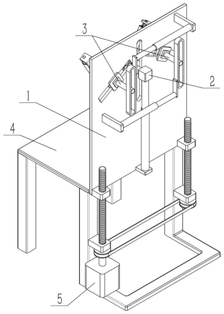
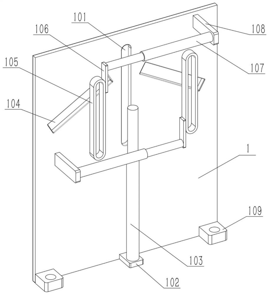
[0029] As shown in the figure, a cervical spine treatment chair for medical care includes a backrest 1, a longitudinal slot 101, a base I102, an electric push rod I103, a vibrating rod 208, a chair surface 4 and a supporting leg 401. The backrest 1 It is arranged on the front side of the seat surface 4, the middle of the upper side of the backrest 1 is provided with a longitudinal notch 101, the base I102 is fixed to the middle of the lower end of the front end of the backrest 1, the electric push rod I103 is fixed to the upper end of the base I102, The movable end of the rod I103 is provided with a connecting piece, the connecting piece passes through the longitudinal slot 101, and two vibrating rods 208 are symmetrically arranged, and the two vibrating rods 208 are fixedly connected to the rear end of the connecting piece. The vibrating rod 208 can be vibrated by a micro-vibration motor, and the motor is wrapped by a tubular member, and the rear end of the tubular member is a...

specific Embodiment approach 2

[0031] As shown, the distance between the two vibrating rods 208 is 5 cm. The distance ensures that the vibration source of the vibrating rods 208 is far away from the spine, thereby preventing the vibrations generated by the two vibrating rods 208 from overlapping at the spine, causing the user to feel uncomfortable or dizzy.

specific Embodiment approach 3

[0033] As shown in the figure, the connecting piece includes a connecting seat 2, a plate I204, a rod I205, a plate II206 and a compression spring I207. The connecting seat 2 is fixed on the movable end of the electric push rod I103, and the plate I204 is arranged on the On the rear side, a rod I205 is slidably connected to the left and right sides of the plate I204, and the front ends of the two rods I205 are fixed to the limiting part I, the rear end of the limiting part I is in contact with the front end of the plate I204, and the plate II206 is fixedly connected At the rear ends of the two rods I 205 , two vibrating rods 208 are fixed to the rear ends of the plates II 206 . When the user leans on the vibrating rod 208, the compression spring I207 is used to make the vibrating rod 208 have a rebound effect, so as to prevent the user from unconsciously pressing on the vibrating rod 208 that cannot be rebounded, although the initial feeling of the heavy pressure is not good. ...


PUM


Abstract

The invention relates to a treatment chair, and in particular relates to a cervical vertebra treatment chair for medical care. The cervical vertebra treatment chair comprises a backrest, a longitudinal notch, a base I, an electric push rod I, a vibrating bar, a chair surface and supporting legs; a massage roller reciprocates obliquely upwards and downwards, so that the levator scapulae, the musculi rhomboideus major, the musculi rhomboideus mino, the supraspinatus and the infraspinatus of a user are rolled; and thus, main muscles at the tension neck and shoulders are stretched and relaxed. Ring pieces making contact with the massage roller are used for providing friction force, so that the massage roller does not roll easily; therefore, rolling becomes the massage effect simulating traditional Chinese medicine; and the nursing relaxation effect is improved. The backrest can be lifted to adapt to people with different heights or different proportions of the upper body and the lower body. When the backrest descends, the massage roller can be utilized for massaging the waist; and the vibrating bar can be utilized for massaging the vicinity of the Yaoyan acupoint.

Description

technical field [0001] The present invention relates to a treatment chair, more particularly to a cervical spine treatment chair for medical care. Background technique [0002] For example, the publication number is CN210044210U. A cervical spine treatment chair for medical care includes a treatment chair seat plate, a chair support rod, a moving wheel, an L-shaped angle plate, a horizontal object plate, a traction belt hook structure that can buffer force measurement, and a height Adjustable handrail structure, backrest board structure with massage function, L-shaped boom rod, nursing tool box, fixed pulley, cervical traction sling, traction hand wheel, cushion cushion and control switch. The arrangement of the right boom rod, the left boom rod, the hanging ring, the traction belt hook, the dynamometer and the buffer spring of the utility model is beneficial to the hooking and fixing of the cervical traction belt, and the tension test can be carried out and the lifting can ...

Claims


Application Information

Patent Timeline
Patent Type & Authority Applications(China)
IPC IPC(8): A61G15/00A61G15/10A61H15/00A61H39/04A61H23/02A61H7/00
CPCA61G15/007A61G15/10A61H15/0078A61H39/04A61H23/02A61H7/007A61H2015/0014A61H2201/0149A61H2201/1207A61H2205/081A61H2205/08
Inventor 王祥林王晓艳孙卫建祝序文杨烁杨鸿亮
Owner HARBIN QUANKE MEDICAL TECH DEV
Why Eureka
Try Eureka