Cleaning and impurity removal equipment and impurity removal method before mica flakes are broken
A technology for cleaning and removing impurities and mica sheets, which is applied in the direction of using liquid cleaning methods, cleaning methods and utensils, chemical instruments and methods, etc., can solve problems such as low efficiency and high labor intensity, achieve convenient recycling, and avoid ore fragmentation Effect
- Summary
- Abstract
- Description
- Claims
- Application Information
AI Technical Summary
Problems solved by technology
Method used
Image
Examples
Embodiment 1
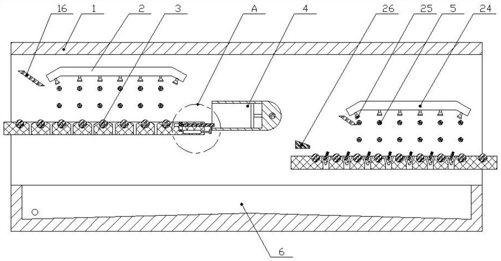
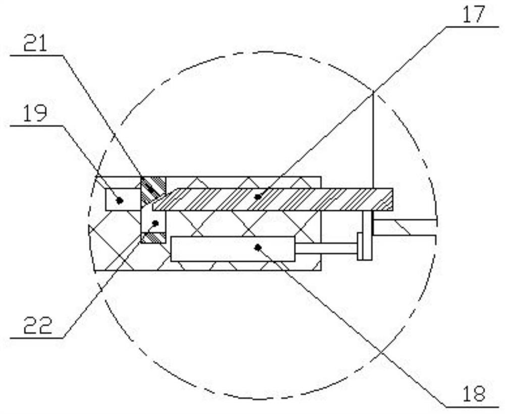
[0028] Example 1: as Figure 1-Figure 3 As shown, the specific structure of this embodiment is as follows: it includes a casing 1, the left and right ends of the casing 1 are respectively set as the feeding end and the discharging end, and at least two cleaning areas are arranged in the casing 1 at intervals. , in this embodiment, two cleaning areas are set, namely the first cleaning area and the second cleaning area, the two cleaning areas are arranged in a stepped shape, the conveying directions of the two cleaning areas are the same, and the first cleaning area is located in the second cleaning area. Obliquely above the cleaning area, each cleaning area includes a spraying device 2 and a conveying part 3 arranged at intervals up and down. The spraying device 2 includes a support 24 and a spray head 25 arranged at the lower end of the support 24. Front and rear in the conveying direction The nozzles 25 at both ends are inclined to the inside of the support 24 to flush the fr...
Embodiment 2
[0030] Example 2: as Figure 3-Figure 6As shown, other structures in this embodiment are the same as in the embodiment, but in this embodiment, the conveying direction of the second cleaning area is opposite to the conveying direction of the first cleaning area. When there are no less than three cleaning areas, the next The conveying direction of the cleaning area is opposite to that of the previous cleaning area, and on the vertical projection plane, some positions of the cleaning area overlap, thereby reducing the footprint of the housing 1. In this embodiment, the first cleaning area is set horizontally. In the second cleaning area, the end of the conveying part 3 is inclined downward and extends to the front side of the upper conveying part 3. The reason why the second cleaning area is set in an inclined state is to prevent the ore from being unable to 100% due to the too large turning angle of the transfer box 4. After the inversion is completed, the height difference bet...
Embodiment 3
[0031] Example 3: as image 3 As shown, other structures in this embodiment are the same as those in Embodiment 1 or Embodiment 2. The upper end of the object carrier 8 is provided with brushes 11 at intervals along its length direction, and the upper end surface of the brush 11 is not lower than the conveying roller 9 The brush 11 includes a mounting plate 12 and bristles 13 fixedly arranged on the upper end of the mounting plate 12 , and the lower end of the mounting plate 12 is clamped into the mounting groove on the upper end of the object carrier 8 .
PUM
 Abstract
Description
Claims
Application Information
 - R&D
- Intellectual Property
- Life Sciences
- Materials
- Tech Scout
- Unparalleled Data Quality
- Higher Quality Content
- 60% Fewer Hallucinations
Browse by: Latest US Patents, China's latest patents, Technical Efficacy Thesaurus, Application Domain, Technology Topic, Popular Technical Reports.
© 2025 PatSnap. All rights reserved.Legal|Privacy policy|Modern Slavery Act Transparency Statement|Sitemap|About US| Contact US: help@patsnap.com


