
Self-clamping-limiting test tube utensil cleaning mechanism applied to clinical laboratory

A technology of cleaning mechanism and inspection department, which is applied in the field of inspection department, can solve the problems of normalized cleaning efficiency, affecting the cleaning effect of test tubes, and many electrical components, so as to reduce practical applications and improve fluency and stability. , the effect of reducing space occupation

Inactive Publication Date: 2020-12-11
泰兴市康森爱特传动设备科技有限公司
View PDF6 Cites 1 Cited by
  • Summary
  • Abstract
  • Description
  • Claims
  • Application Information

AI Technical Summary

Problems solved by technology

[0007] The purpose of the present invention is to provide a test tube utensil cleaning mechanism using self-clamping and limiting in the laboratory to solve the above-mentioned background technology. It is proposed that the existing test tube utensil cleaning mechanism needs artificial auxiliary installation and positioning of the placed test tube utensils, which is easy to cause The positioning during the cleaning process is loose, resulting in shaking and collision damage to the test tube apparatus during cleaning. At the same time, the artificial clamping and positioning affect the cleaning effect of the test tube and easily cause local damage to the test tube. The structure of the electrical components used is high, and the use cost is high. At the same time, it is easy to cause potential safety hazards in the use of electricity during the long-term use of the equipment and the efficiency of normalized cleaning

Method used


Image

  • Self-clamping-limiting test tube utensil cleaning mechanism applied to clinical laboratory
  • Self-clamping-limiting test tube utensil cleaning mechanism applied to clinical laboratory
  • Self-clamping-limiting test tube utensil cleaning mechanism applied to clinical laboratory

Examples


Embodiment Construction

[0027] The following will clearly and completely describe the technical solutions in the embodiments of the present invention with reference to the accompanying drawings in the embodiments of the present invention. Obviously, the described embodiments are only some, not all, embodiments of the present invention. Based on the embodiments of the present invention, all other embodiments obtained by persons of ordinary skill in the art without making creative efforts belong to the protection scope of the present invention.

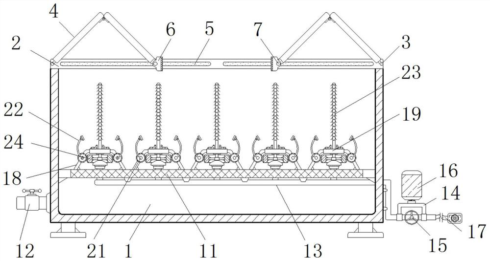
[0028] see Figure 1-6 , the present invention provides a technical solution: a test tube utensil cleaning mechanism that uses self-clamping and limiting in laboratory, including a housing 1, a side slat 2, a first cross bar 3, a sealing plate 4, a chute 5, and a sealing strip 6 , second cross bar 7, motor 8, worm screw 9, worm gear 10, grid plate 11, blowdown valve 12, diversion pipe 13, shunt pipe 14, blocking valve 15, solvent bottle 16, miniature water pum...


PUM


Abstract

The invention discloses a self-clamping-limiting test tube utensil cleaning mechanism applied to the clinical laboratory. The self-clamping-limiting test tube utensil cleaning mechanism comprises a shell, a motor, a micro water pump and supports, side battens are symmetrically installed on the edge of the top of the shell, sliding grooves are formed in the inner side walls of the side battens, andthe interiors of the sliding grooves are connected with the ends of second transverse rods. The second transverse rods and the ends of sealing strips and sealing plates are installed in a penetratingmanner, the motor is fixedly installed on the top of the back face of the shell, a grid plate is fixedly installed in the shell, a blow-down valve is fixed to the position, below the grid plate, of the outer wall of the shell in a penetrating manner, and a flow dividing pipe is connected to the outer wall, on the outer side of the shell, of a flow guiding pipe in a penetrating manner. According to the self-clamping-limiting test tube utensil cleaning mechanism applied to the clinical laboratory, opening and closing of the mechanism are facilitated, the occupied space for opening and closing is reduced, auxiliary clamping and positioning of test tubes are facilitated, the positioning stability and the cleaning efficiency are improved, and collision damage in the cleaning process is avoided.

Description

technical field [0001] The invention relates to the related technical field of laboratories, in particular to a test tube utensil cleaning mechanism using self-clamping and limiting for laboratories. Background technique [0002] In the daily work and application of the medical laboratory, test tubes are often used for inspection and testing of pharmaceuticals and solutions. In order to improve the accuracy of the test and avoid the invalidation of test data caused by solution residues, it is necessary to clean the inside of the test tube after use. , maintain the cleanliness of its interior, reduce the manual labor consumption of test tube utensils by setting up auxiliary cleaning mechanisms, improve the cleanliness of test tube utensils, and effectively reduce the phenomenon of wall hanging and water droplets on the inner wall of test tube utensils after cleaning . [0003] However, the existing test tube utensil cleaning mechanism has the following new problems in use: ...

Claims


Application Information

Patent Timeline
Patent Type & Authority Applications(China)
IPC IPC(8): B08B9/20B08B9/28B08B9/36
CPCB08B9/20B08B9/28B08B9/36
Inventor 周再辉
Owner 泰兴市康森爱特传动设备科技有限公司
Learn More