Rectangular iron sheet punching equipment
A technology of rectangular and iron sheets, which is applied in the field of rectangular iron sheet punching equipment, can solve problems such as hand injuries, and achieve the effects of increasing safety, saving cutting time, and facilitating reuse
- Summary
- Abstract
- Description
- Claims
- Application Information
AI Technical Summary
Problems solved by technology
Method used
Image

Examples
Embodiment 1
[0022] Such as figure 1 As shown, a rectangular iron sheet punching equipment includes a base 1, a servo motor 2, a punching mechanism 3 and a pulley assembly 4, a servo motor 2 is arranged on the left side of the top of the base 1, and a punching mechanism is arranged in the middle of the top of the base 1 3. A pulley assembly 4 is wound between the output shaft of the servo motor 2 and the punching mechanism 3 .
[0023] When it is necessary to punch a rectangular iron sheet, first, the staff places the rectangular iron sheet on the punching mechanism 3, then starts the servo motor 2, and the output shaft of the servo motor 2 drives the punching mechanism 3 to the rectangular iron sheet through the pulley assembly 4. The iron sheet is punched. During the punching process, the staff moves the rectangular iron sheet to facilitate the punching mechanism 3 to punch holes on each position of the rectangular iron sheet. After the rectangular iron sheet is punched, the servo motor ...
Embodiment 2
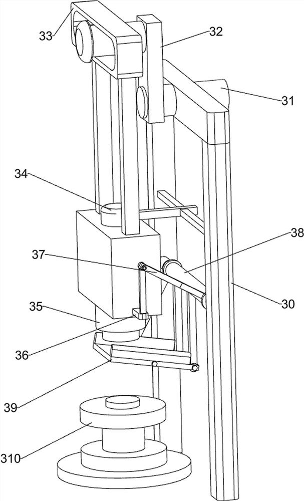
[0025] Such as figure 2 As shown, a rectangular iron sheet punching equipment, on the basis of Embodiment 1, the punching mechanism 3 includes a first bracket 30, a first rotating shaft 31, a first rotating block 32, a first pushing assembly 33, Guide block 34, punch 35, fixed block 36, connecting block 37, second rotating shaft 38, receiving plate 39 and support table 310, base 1 top front side is provided with first support 30, and the first support 30 upper end rotation type is arranged There is a first rotating shaft 31, the front end of the first rotating shaft 31 is connected with the output shaft of the servo motor 2 through the pulley assembly 4, the rear end of the first rotating shaft 31 is provided with a first rotating block 32, and the rear end of the first rotating block 32 is sliding A first push assembly 33 is provided, and a chute is provided on the first push assembly 33. The first rotating block 32 cooperates with the chute of the first push assembly 33. A ...
Embodiment 3
[0028] Such as figure 1 , image 3 , Figure 4 and Figure 5As shown, a rectangular iron sheet punching equipment, on the basis of Embodiment 1 and Embodiment 2, also includes a storage box 5, the front side of the top of the base 1 is provided with a storage box 5, and one side of the storage plate 39 is located box 5 above.
[0029] After the remaining material falls on the receiving plate 39, the remaining material slides forward along the slope of the receiving plate 39 and falls into the storage box 5, so that the staff can collect the remaining material.
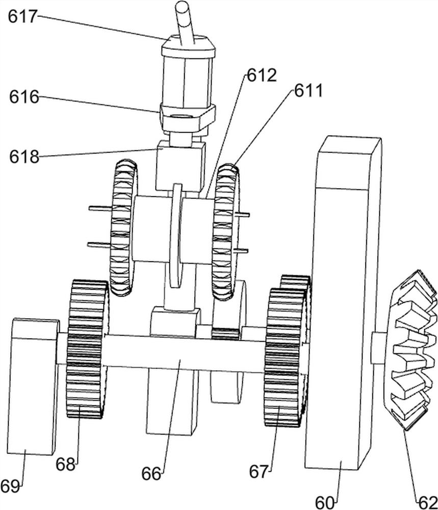
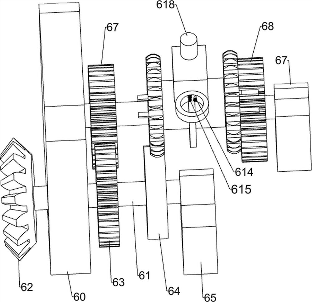
[0030] Also include a propulsion mechanism 6, the propulsion mechanism 6 includes a support block 60, a third rotating shaft 61, a bevel gear 62, a first gear 63, a missing gear 64, a second support 65, a fourth rotating shaft 66, and a second gear 67 , the third gear 68, the third bracket 69, the threaded rod 610, the fourth gear 611, the guide assembly 612, the fourth bracket 613, the block 614, the spring 615, t...
PUM
 Abstract
Description
Claims
Application Information
 - R&D
- Intellectual Property
- Life Sciences
- Materials
- Tech Scout
- Unparalleled Data Quality
- Higher Quality Content
- 60% Fewer Hallucinations
Browse by: Latest US Patents, China's latest patents, Technical Efficacy Thesaurus, Application Domain, Technology Topic, Popular Technical Reports.
© 2025 PatSnap. All rights reserved.Legal|Privacy policy|Modern Slavery Act Transparency Statement|Sitemap|About US| Contact US: help@patsnap.com