
Rear axle flange ring welding device with adjusting structure and for automobile

A technology for adjusting structures and welding devices, applied in auxiliary devices, welding equipment, auxiliary welding equipment, etc., can solve the problems of increasing the welding difficulty of welding personnel, prone to slipping, and unable to fix the drive axle housing of the rear axle, etc., to achieve reduction Risk of burns, avoidance of turning and slipping, effect of reducing difficulty of operation

Active Publication Date: 2020-12-11
CHANGDE JIAHONG MACHINERY
View PDF7 Cites 1 Cited by
  • Summary
  • Abstract
  • Description
  • Claims
  • Application Information

AI Technical Summary

Problems solved by technology

[0003] However, the drive axle housing of the rear axle cannot be fixed when supported by the "Y"-shaped support frame, and it is easy to slip during the welding process, thereby increasing the welding difficulty of the welding personnel. Moreover, the height of the support frame cannot be adjusted during support. Adjust, so that when welding the bottom of the flange ring, the welder needs to lie on the ground to operate, with his face facing upward, so that welding stars can easily splash on the face of the welder and cause burns

Method used


Image

  • Rear axle flange ring welding device with adjusting structure and for automobile
  • Rear axle flange ring welding device with adjusting structure and for automobile
  • Rear axle flange ring welding device with adjusting structure and for automobile

Examples


Embodiment 1

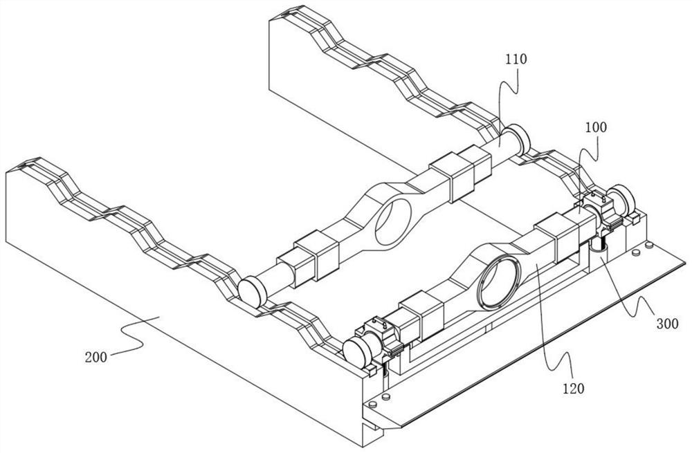
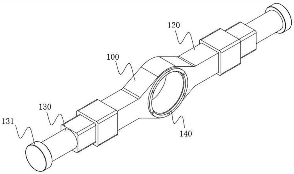
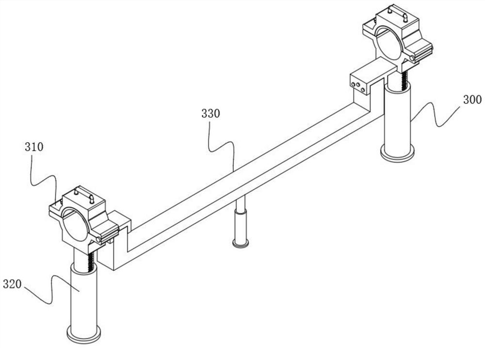
[0069] The invention provides a rear axle flange welding device with an adjustment structure for automobiles, please refer to Figure 1-Figure 17 , including a rear axle 100 and a welding frame 200 arranged at the bottom of the rear axle 100, the welding frame 200 includes two support plates 210, and the two support plates 210 are respectively arranged on the left and right sides of the rear axle 100, and the rear axle 100 includes a drive axle housing 130 , a wheel hub 131 is provided at the end of the drive axle housing 130 , and an adjustment mechanism 300 is provided between the two support plates 210 near the front side.

[0070] It should be noted that the rear axle 100 is provided with the rear axle 110 to be welded and the welded rear axle 120 during the welding process, please refer to figure 1 As shown, the front side is the welded rear bridge 120, and the rear side is the rear bridge 110 to be welded.

[0071] In addition, the adjustment mechanism 300 includes at l...


PUM


Abstract

The invention relates to the technical field of flange ring welding, in particular to a rear axle flange ring welding device with an adjusting structure and for an automobile. The rear axle flange ring welding device comprises a rear axle and a welding frame arranged at the bottom of the rear axle. The welding frame comprises two supporting plates, the two supporting plates are correspondingly arranged on the left side and the right side of the rear axle, the rear axle comprises a drive axle housing, a hub is arranged at the end of the drive axle housing, and an adjusting mechanism is arrangedat the position, close to the front side, between the two supporting plates. A fixing device is arranged, the drive axle housing is fixed through static friction force generated by an anti-skid pad and a bottom fixing groove, the phenomena of rotation and skid of the drive axle housing are avoided, and the operation difficulty of welding personnel during welding is reduced; and the height of thewelding rear axle is adjusted through a telescopic cross beam, so that the welding position at the bottom is flush with the face of the welding personnel, the splashing amount of welding sparks flyingto the face is reduced, and the risk that the face is scalded by the welding sparks is reduced.

Description

technical field [0001] The invention relates to the technical field of flange ring welding, in particular to a rear axle flange ring welding device with an adjusting structure for automobiles. Background technique [0002] The reducer and differential of the car need to be fixed in the middle of the rear axle through the flange ring, so the flange ring needs to be welded on the rear axle first. Since the drive axle housing of the rear axle is a cylindrical structure, it is usually welded The drive axle housing is supported by two "Y"-shaped support frames to achieve the purpose of supporting the rear axle, and then welded. [0003] However, the drive axle housing of the rear axle cannot be fixed when supported by the "Y"-shaped support frame, and it is easy to slip during the welding process, thereby increasing the welding difficulty of the welding personnel. Moreover, the height of the support frame cannot be adjusted during support. Adjust, so that when welding the bottom...

Claims


Application Information

Patent Timeline
Patent Type & Authority Applications(China)
IPC IPC(8): B23K37/04B23K37/00
CPCB23K37/0461B23K37/00
Inventor 谭宇岐铁钟杨德华
Owner CHANGDE JIAHONG MACHINERY
Learn More