Sand prevention and filling integrated wellhead device

A wellhead device and body technology, applied in the direction of mining fluid, wellbore/well components, earthwork drilling and mining, etc., can solve problems such as heavy workload, frequent construction, and potential safety hazards in construction, and achieve good pressure-resistant rotation and sliding effects , reduce construction risk, excellent filtering effect

Inactive Publication Date: 2020-12-11
东营市正能石油科技有限公司
View PDF1 Cites 9 Cited by
  • Summary
  • Abstract
  • Description
  • Claims
  • Application Information

AI Technical Summary

Problems solved by technology

[0003] At present, the wellheads used for fracturing and sand control operations are all fixed wellheads, which have a series of problems such as complicated installation and disassembly
When it is necessary to reverse the pipeline to backwash the well after the fracturing filling is completed, the single-layer filling needs to be lifted and discarded, and the layered sand control needs to be lifted to change the layer construction, and the fixed wellhead obviously cannot meet the requirements
First of all, the fixed wellhead is inconvenient to operate and has potential safety hazards in construction
Secondly, in the construction of layered sand control and layer replacement, the base flange needs to be disassembled when the pipe string is lifted, which requires a lot of work, takes a long time, and there is a risk of sand stuck in the pipe string, which poses a great safety hazard
Third, if the backwash is blocked during single-layer packing and the pipe string needs to be lifted quickly, the existing wellhead structure cannot meet the requirements
[0004] The patent No. CN111236886A discloses a floating rotary sliding sand control wellhead device and method, including a sliding wellhead, a rotating wellhead, a connecting manifold and a construction control manifold. The sliding wellhead includes a lower joint, a bottom flange, The quick-installation cap, the center pipe, the center pipe passes through the quick-installation cap and the bottom flange to connect with the lower joint, the other end of the lower joint is connected to the construction tubing, and the bottom flange is connected to the construction wellhead flange, so that the oil casing annulus in the well forms a In a closed space, the upper end of the center pipe is connected to the well control valve; the rotary wellhead includes a tubing nipple, a rotary nipple, and a load-bearing swivel joint; the upper end of the well control valve is connected to the tubing nipple; the upper end of the tubing nipple is connected to the rotary nipple; The upper end of the swivel joint is connected to the load-bearing swivel joint; although the sand control wellhead device Su disclosed in this invention has better pressure-resistant rotation and sliding effects, the sand control effect of the wellhead device is poor, and the wellhead device needs to be dredged frequently , its construction is frequent and the workload is heavy

Method used


Image

  • Sand prevention and filling integrated wellhead device
  • Sand prevention and filling integrated wellhead device
  • Sand prevention and filling integrated wellhead device

Examples


Embodiment 1

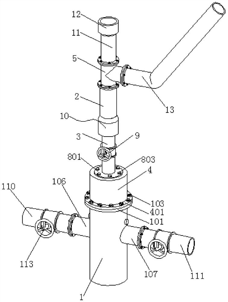
[0039] This Example 1 introduces an integrated wellhead device for sand control and filling, refer to the attached figure 1 , its main structure includes a wellhead body 1, an upper center pipe 2, a lower center pipe 3, a wellhead connection cover 4 and a pipe connection tee 5.

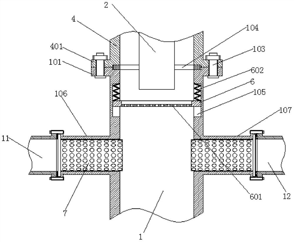
[0040] Reference attached figure 2 And attached Figure 4 The upper end surface of the wellhead body 1 is connected with a wellhead flange 101, the inner surface of the wellhead flange 101 is provided with a first sealing ring groove 102, and the lower end opening of the wellhead connection cover body 4 is provided with a cover body flange 401, the cover body method The inner surface of the flange 401 is provided with a second sealing ring groove 402 corresponding to the first sealing ring groove 102. The wellhead flange 101 and the housing body flange 401 are tightly connected by bolts 103, and the first sealing ring is recessed. A large rubber sealing ring 104 is arranged between the groove 102 a...

Embodiment 2

[0046] This embodiment 2 introduces the improved integrated wellhead device for sand control and packing based on the embodiment 1.

[0047] First of all, the similarities between Embodiment 2 and Embodiment 1 will not be described again here, and the differences of Embodiment 2 will be described in detail below:

[0048] First, referring to the accompanying drawings, 8 and attached Figure 9 , in this embodiment 2, it is not a direct sleeve pipe, the entire rotating connecting pipe assembly 10 includes a rotating sleeve joint 14, the rotating sleeve joint 14 is integrally connected with the lower end of the upper central pipe 2, and the upper end of the inner wall of the rotating sleeve joint 14 A swivel bearing 15 is provided, and the top outer wall of the lower center tube 3 is welded to the inner cavity of the swivel bearing 15 , and a retaining ring 16 is arranged in the gap between the swivel sleeve joint 14 and the lower central tube 3 . Further, the top end of the low...


PUM


Abstract

The invention relates to the technical field of oil exploitation equipment, and particularly relates to a sand prevention and filling integrated wellhead device. The sand prevention and filling integrated wellhead device comprises a wellhead body, an upper central pipe, a lower central pipe, a wellhead connecting cover body and a pipeline connecting tee joint, wherein the upper end face of the wellhead body is connected with a wellhead flange; a first sealing ring groove is formed in the inner side face of the wellhead flange; a cover body flange is arranged at an opening in the lower end of the wellhead connecting cover body; and the wellhead flange and the cover body flange are connected in a fastened mode through bolts. The sand prevention and filling integrated wellhead device has better pressure-resistant rotating and sliding effects, can turn flexibly and is resistant to impact, vibration and high temperature and high pressure; an annular screen frame is arranged at the upper endof the wellhead body, a sand prevention screen is arranged on the annular screen frame and can filter sand mixed in gushing liquid, and thus the sand prevention effect is achieved; and in addition, the annular screen frame vibrates up and down in the construction process, the sand prevention screen can be effectively prevented from being blocked by the sand, and the oil outlet amount of the sandprevention screen is not affected.

Description

technical field [0001] The invention relates to the technical field of oil exploitation equipment, in particular to an integrated wellhead device for sand control and filling. Background technique [0002] As the oilfield development enters the middle and late stages, formation sand production is increasing day by day. The adjustment and development of subdivided strata has greatly increased the number of multi-layer wells, and the layered fracturing sand control technology can carry out targeted transformation and sand control construction on the entire stratum, and ensure that each layer is independent of each other. Scope promotion. [0003] At present, the wellheads used for fracturing and sand control operations are all fixed wellheads, which have a series of problems such as complicated installation and disassembly. When it is necessary to reverse the pipeline and backwash the well after the fracturing filling is completed, the single-layer filling needs to be lifted...

Claims


Application Information

Patent Timeline
Patent Type & Authority Applications(China)
IPC IPC(8): E21B33/03E21B43/08
CPCE21B33/03E21B43/086
Inventor 不公告发明人
Owner 东营市正能石油科技有限公司
Why Eureka
Try Eureka