
Transmission structure for wind driven generator

A technology for wind turbines and transmission structures, which is applied to wind turbines, wind energy power generation, engines, etc., can solve the problems of non-uniform structure of wind transmission structures and high maintenance costs, so as to reduce maintenance and repair costs, improve uniformity, and improve applicability. range effect

Active Publication Date: 2020-12-11
NORTH CHINA UNIVERSITY OF SCIENCE AND TECHNOLOGY
View PDF11 Cites 0 Cited by
  • Summary
  • Abstract
  • Description
  • Claims
  • Application Information

AI Technical Summary

Problems solved by technology

[0005] The purpose of the present invention is to provide a transmission structure for wind power generators to solve the technical problems of non-uniform wind power transmission structures and high maintenance costs in the prior art

Method used


Image

  • Transmission structure for wind driven generator
  • Transmission structure for wind driven generator
  • Transmission structure for wind driven generator

Examples


Embodiment Construction

[0022] The technical solutions of the present invention will be clearly and completely described below in conjunction with the accompanying drawings. Apparently, the described embodiments are some of the embodiments of the present invention, but not all of them.

[0023] The components of the embodiments of the invention generally described and shown in the figures herein may be arranged and designed in a variety of different configurations. Accordingly, the following detailed description of the embodiments of the invention provided in the accompanying drawings is not intended to limit the scope of the claimed invention, but merely represents selected embodiments of the invention.

[0024] Based on the embodiments of the present invention, all other embodiments obtained by persons of ordinary skill in the art without making creative efforts belong to the protection scope of the present invention.

[0025] In the description of the present invention, it should be noted that the...


PUM


Abstract

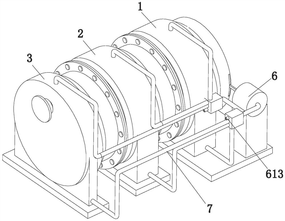
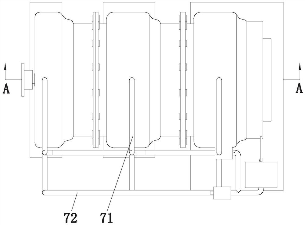
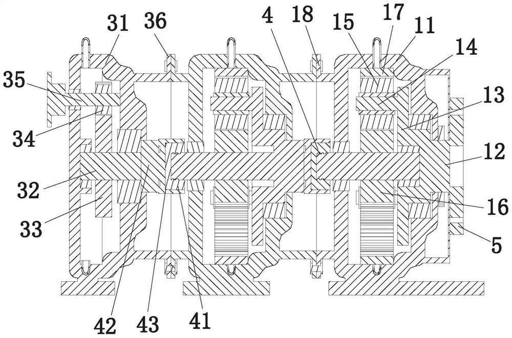
The invention discloses a transmission structure for a wind driven generator, and belongs to the field of wind power transmission equipment. The transmission structure comprises a first transmission mechanism, a second transmission mechanism and a third transmission mechanism, wherein connecting assemblies for connecting the first transmission mechanism and the second transmission mechanism as well as the second transmission mechanism and the third transmission mechanism are arranged between the first transmission mechanism and the second transmission mechanism as well as between the second transmission mechanism and the third transmission mechanism; a shaft flange is arranged at the front end of the first transmission mechanism; a lubricating mechanism is arranged beside the first transmission mechanism; and lubricating assemblies which are matched with the lubricating mechanism are arranged beside the second transmission mechanism and the third transmission mechanism. According to the transmission structure disclosed by the invention, the first transmission mechanism, the second transmission mechanism and the third transmission mechanism are connected, so that a corresponding damaged part is conveniently and quickly replaced during maintenance and repair, and therefore, maintenance and repair cost can be reduced; and moreover, the number of the second transmission mechanismsand the number of the third transmission mechanisms can be increased or decreased according to terrain, height and wind power conditions, so that the transmission structure is suitable for being usedin different places.

Description

technical field [0001] The invention relates to the field of wind power transmission equipment, in particular to a transmission structure for a wind power generator. Background technique [0002] The wind power transmission structure is a commonly used power transmission structure for wind turbines, mainly to transfer the kinetic energy of the fan blade rotation to the power generation equipment for power generation. [0003] Existing wind power transmission structures are realized through planetary gear structures and variable speed gear structures. During use, multiple planetary gear structures and variable speed gear structures are usually used to work together. gearbox, which mainly includes the first-stage sun gear, the first-stage planetary gear, the second-stage planetary gear, the middle bull gear, the second-stage sun gear, and the first-stage sun gear, and is characterized in that: the first-stage sun gear is connected to the The input shaft is connected, the firs...

Claims


Application Information

Patent Timeline
Patent Type & Authority Applications(China)
IPC IPC(8): F03D15/00F03D80/70
CPCF03D15/00F03D80/70Y02E10/72
Inventor 张怡吴宝江张执超屈滨
Owner NORTH CHINA UNIVERSITY OF SCIENCE AND TECHNOLOGY
Learn More