an impeller
A technology of impeller and deflector, which is applied in the fields of impeller, fluid conveying device, and DC conical centrifugal impeller. It can solve the problems of small volume, large air volume and wind pressure, and achieve the effects of small volume, high efficiency and high pressure.
- Summary
- Abstract
- Description
- Claims
- Application Information
AI Technical Summary
Problems solved by technology
Method used
Image
Examples
Embodiment 1
[0034] Embodiment 1 (impeller without housing)
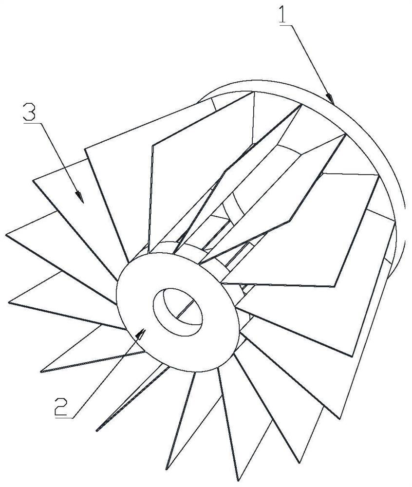
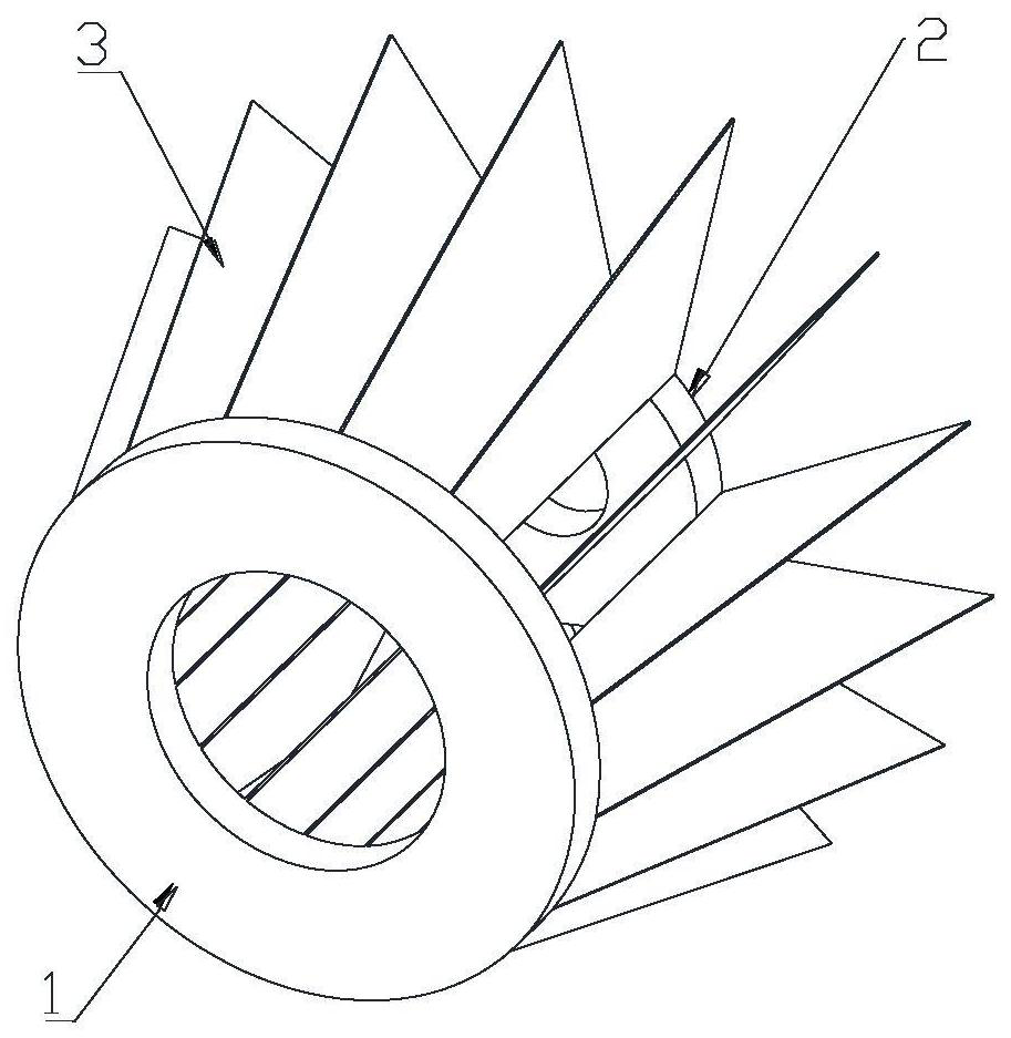
[0035] see figure 1 , figure 2 , Figure 5 , Figure 6 and Figure 7 , the present embodiment provides an impeller, including a front disc, a rear disc, and guide vanes distributed in an array between the front disc and the rear disc, the guide vanes are trapezoidal straight plates, and one end of the upper bottom of the guide vanes It is connected with the end face of the front plate, and one end of the lower bottom edge of the guide vane is connected with the rear plate.
[0036] The end faces where the upper bottom edge of the deflector is located are all located on the annular end face of the front plate; the outer surface of the rear plate is connected with the inner wall of the deflector near the lower bottom edge; both the front plate and the rear plate are annular plates, and the center hole of the front plate is the fluid input port (see Figure 7 , if the fluid is gas and the impeller is used as a fan impeller, ...
Embodiment 2
[0042] Embodiment 2 (impeller with casing)
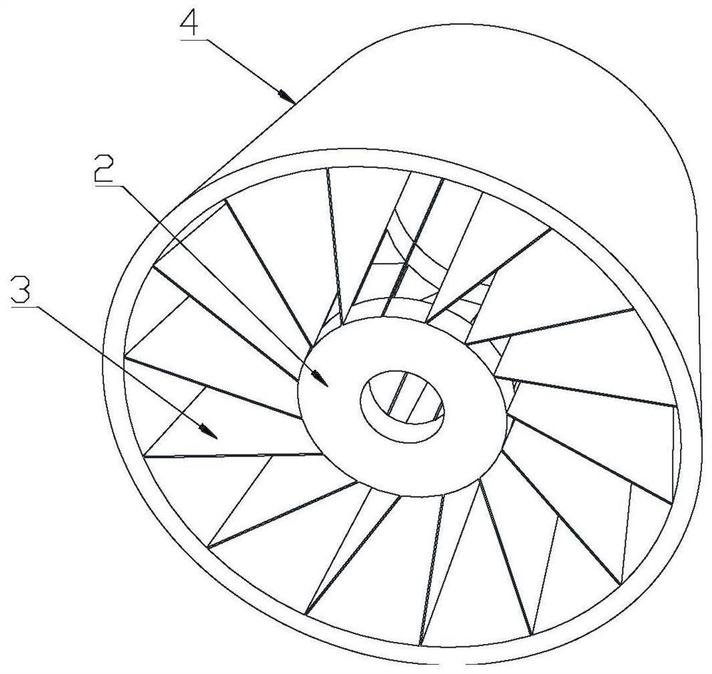
[0043] see image 3 , Figure 4 , Figure 5 and Figure 6, the present embodiment provides an impeller, including a front disc, a rear disc, and guide vanes distributed in an array between the front disc and the rear disc, the guide vanes are trapezoidal straight plates, and one end of the upper bottom of the guide vanes It is connected with the end face of the front plate, and one end of the lower bottom edge of the guide vane is connected with the rear plate.
[0044] The end faces where the upper bottom edge of the deflector is located are all located on the annular end face of the front plate; the outer surface of the rear plate is connected with the inner wall of the deflector near the lower bottom edge; both the front plate and the rear plate are annular plates, and the center hole of the front plate is the fluid input port (if the fluid is gas and the impeller is used as a fan impeller, the input port is the air inlet), a...
Embodiment 3
[0052] On the basis of Embodiment 1 or 2, the number of guide vanes is further limited; the number of guide vanes is 2-1200 pieces, preferably, the number of guide vanes needs to be determined according to the maximum diameter of the impeller, and the maximum diameter of the impeller The ratio to the number of leaves is 5:1.
PUM
 Abstract
Description
Claims
Application Information
 - R&D
- Intellectual Property
- Life Sciences
- Materials
- Tech Scout
- Unparalleled Data Quality
- Higher Quality Content
- 60% Fewer Hallucinations
Browse by: Latest US Patents, China's latest patents, Technical Efficacy Thesaurus, Application Domain, Technology Topic, Popular Technical Reports.
© 2025 PatSnap. All rights reserved.Legal|Privacy policy|Modern Slavery Act Transparency Statement|Sitemap|About US| Contact US: help@patsnap.com


