A Long Straight Wing Dynamically Coupled Wind Tunnel Test Model with Drag Rudder

A technology of wing dynamics and wind tunnel testing, which is applied in aerodynamic testing, machine/structural component testing, aircraft component testing, etc. It can solve complex theoretical calculations, less consideration of rudder deflection angle, and difficulty in studying wing dynamics academic characteristics etc.

Active Publication Date: 2021-07-09
NANJING UNIV OF AERONAUTICS & ASTRONAUTICS
View PDF5 Cites 0 Cited by
  • Summary
  • Abstract
  • Description
  • Claims
  • Application Information

AI Technical Summary

Problems solved by technology

Generally speaking, in the method of obtaining the vibration characteristics of tailless aircraft wings with drag rudders, theoretical calculations are too complicated, and wind tunnel tests are indispensable. Most of the existing wing aeroelastic models use a main beam Simulate the stiffness of the wing, use the frame section to simulate the shape, and use the counterweight to simulate the mass distribution. The influence of the deflection angle of the rudder surface on the vibration characteristics of the wing is seldom considered or even not considered. It is difficult to study the Detailed dynamics of the wing

Method used


Image

  • A Long Straight Wing Dynamically Coupled Wind Tunnel Test Model with Drag Rudder
  • A Long Straight Wing Dynamically Coupled Wind Tunnel Test Model with Drag Rudder
  • A Long Straight Wing Dynamically Coupled Wind Tunnel Test Model with Drag Rudder

Examples


Embodiment Construction

[0033] In order to make the object, technical solution and effect of the present invention clearer and clearer, the following examples are given to further describe the present invention in detail. It should be pointed out that the specific implementations described here are only used to explain the present invention, not to limit the present invention.

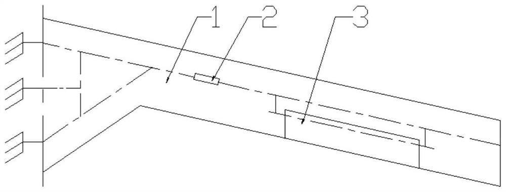
[0034] Such as figure 1 Shown is the top view of the wing and the resistance rudder in the wind tunnel elastic model of the tailless aircraft of the present invention, including the wing 1, and the model stiffness adjustment device 2 and the resistance rudder 3 are arranged on the wing 1, and the resistance rudder 3 Including resistance rudder steering stiffness adjustment device, deflection angle control device and resistance rudder rudder surface model.

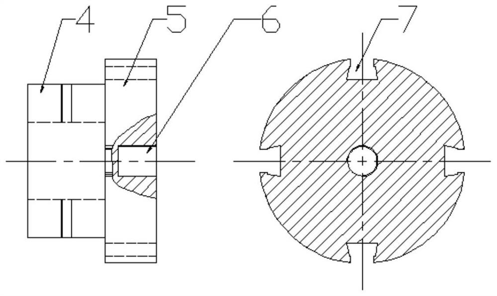
[0035] Such as Figure 2~8As shown, the model stiffness adjusting device 2 of the present invention includes a left connecting plate, a right connecting plate, a variabl...


PUM


Abstract

The invention discloses a long straight wing dynamic coupling wind tunnel test model with a drag rudder, belongs to the technical field of tailless aircraft aeroelastic wind tunnel model, and is a large aspect ratio wing with a cracked drag rudder Dynamic coupling characteristic wind tunnel test model, the present invention comprises basic model, wing stiffness adjustment device, rudder surface control stiffness adjustment device and rudder surface deflection angle control device; Because the change of tailless aircraft wing stiffness distribution can cause its natural frequency The change of the rudder affects its vibration characteristics; changing the steering stiffness of the drag rudder can be used to change the vibration characteristics of the rudder surface, and changing the deflection angle of the rudder surface can be used to change the strength of the attached vortex. Therefore, the device of the invention can be used to study the dynamic coupling characteristics of a wing with a split drag rudder and a large aspect ratio.

Description

technical field [0001] The invention relates to the technical field of aeroelastic wind tunnel models of tailless aircraft, and relates to a long straight wing dynamic coupling wind tunnel test model with drag rudders, in particular to a large aspect ratio wing with split drag rudders Dynamically coupled characteristics of a wind tunnel test model. Background technique [0002] In order to obtain better stealth performance, the tailless aircraft adopts wing-body fusion technology, and abandons the vertical and horizontal tails. At the same time, the disadvantage is that its directional control characteristics are insufficient. At present, drag rudder is one of the most effective directional control methods for tailless aircraft, which generally refers to the trailing edge cracked drag rudder installed on the wingtip. For a tailless aircraft with a flying wing layout with a large aspect ratio, the small resistance on the drag rudder can generate sufficient yaw moment; in add...

Claims


Application Information

Patent Timeline
Patent Type & Authority Patents(China)
IPC IPC(8): G01M9/08B64F5/60
CPCB64F5/60G01M9/08
Inventor 周丽周大恒施远邱涛
Owner NANJING UNIV OF AERONAUTICS & ASTRONAUTICS
Why Eureka
Try Eureka