High-pass radio frequency filter

A radio frequency filter, high-pass technology, applied in the field of filters, can solve the problems of large space ratio, affecting the intermodulation and insertion loss of cavity filters, the distance can not meet the predetermined requirements, etc., to achieve more resonant frequency selection, stable filtering work , to avoid the effect of tip discharge

Inactive Publication Date: 2020-12-11
安徽蓝讯电子科技有限公司
View PDF6 Cites 2 Cited by
  • Summary
  • Abstract
  • Description
  • Claims
  • Application Information

AI Technical Summary

Problems solved by technology

This method has the following disadvantages: 1) For a relatively small cavity, the space occupied by the installation boss is relatively large, which will increase the insertion loss of the cavity filter; 2) The difference between the resonant column and the installation boss The contact surface is uneven, resulting in poor contact between the two, which in turn affects the intermodulation and insertion loss of the cavity filter
3) There will be a certain assembly error in the resonant column, so that the distance between the adjacent resonant column and the flying rod cannot meet the predetermined requirements, which will affect the coupling index between the resonant column and the flying rod
Although this method overcomes the problems of the first solution, it also has the following defects: 1) The resonant column must be made of aluminum alloy material like the cavity, and the volume of aluminum alloy is affected by temperature changes It is very large, so for some cavity filters with relatively high temperature drift requirements, it cannot be manufactured in this way
2) The tuning screw is located in the resonant cavity and is capacitively coupled with the resonant column. Since the thread part on the outer surface of the tuning screw is relatively sharp, it will cause discharge at the tip, and then generate power ignition
3) Due to the complex structure of the cavity, the requirements for the stamping die are relatively high

Method used


Image

  • High-pass radio frequency filter
  • High-pass radio frequency filter
  • High-pass radio frequency filter

Examples


Embodiment Construction

[0018] The present invention will be further described in detail below in conjunction with the accompanying drawings and specific embodiments. The embodiments of the present invention have been presented for purposes of illustration and description, but are not intended to be exhaustive or to limit the invention to the form disclosed. Many modifications and changes will be apparent to those of ordinary skill in the art. The embodiment was chosen and described in order to better explain the principles of the invention and the practical application, and to enable others of ordinary skill in the art to understand the invention and design various embodiments with various modifications as are suited to the particular use.

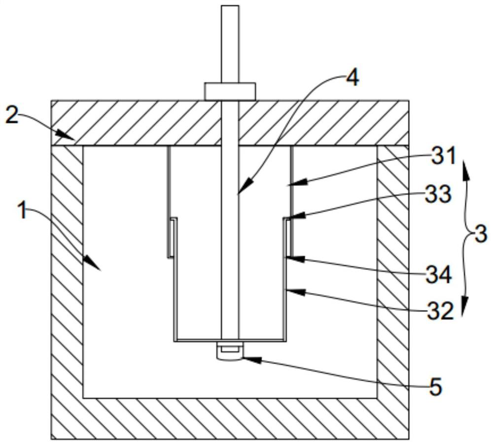
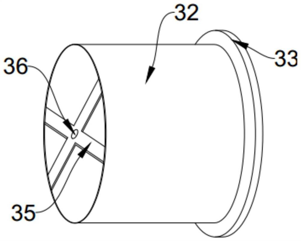
[0019] Such as figure 1 As shown, the technical solution of the present invention is a high-pass radio frequency filter, which includes a resonant cavity 1 , a cover plate 2 and a resonant column 3 placed in the resonant cavity 1 . The length of the resonance ...


PUM


Abstract

The invention relates to a high-pass radio frequency filter, which comprises a resonant cavity, a cover plate and a resonant column arranged in the resonant cavity, the length of the resonant column is adjustable, a tuning screw rod is connected to the resonant column, the tuning screw rod penetrates out of the cover plate, and the resonant column participates in working length adjustment in the resonant cavity. The resonance column comprises a fixed part fixedly connected with the inner surface of the cover plate and a movable part sleeved with the fixed part, and the movable part is fixedlyconnected with the tuning screw rod; according to the high-pass radio frequency filter, the arrangement of various structures and components in the resonant cavity of the filter in the prior art is solved, the existence of sharp corners in one or the cavity is avoided, and meanwhile, the length of the resonant column is adjustable, and the output frequency is high.

Description

technical field [0001] The invention belongs to the field of filters, and more specifically designs a high-pass radio frequency filter. Background technique [0002] As a frequency selection device, the cavity filter is used to select the frequency of communication signals and filter out clutter or interference signals other than the frequency of communication signals, and is widely used in various signal base stations. Existing cavity filters generally include a cavity and a cover plate. The cover plate seals the cavity to form a resonant cavity. The bottom of the resonant cavity is provided with a resonant column protruding toward the cover plate. The resonant column is in the shape of a cylinder with one end closed and the other open. . A tuning screw protruding into the resonant column is provided on the cover plate to adjust the frequency of the cavity filter. [0003] There are two existing installation methods for the resonant column. The first method is: first punc...

Claims


Application Information

Patent Timeline
Patent Type & Authority Applications(China)
IPC IPC(8): H01P1/207
CPCH01P1/207
Inventor 尹桂芳汪海港张主霖
Owner 安徽蓝讯电子科技有限公司
Why Eureka
Try Eureka