Direct-current speed reduction motor with multiple stages of speed reduction gears

A technology of DC deceleration motor and deceleration gear, which is applied in the direction of gear transmission, belt/chain/gear, electromechanical device, etc. It can solve the problems of increased workload, complicated installation of gearbox, and troublesome disassembly and assembly of gearbox, so as to reduce labor force The output, convenient disassembly, and the effect of reducing the installation process

Pending Publication Date: 2020-12-11
JIANGSU SANJIANG DISHENG MOTOR CO LTD
View PDF0 Cites 0 Cited by
  • Summary
  • Abstract
  • Description
  • Claims
  • Application Information

AI Technical Summary

Problems solved by technology

[0003] The DC deceleration motor is also a kind of motor. It uses multi-stage reduction gears to cooperate with the transmission to achieve the effect of deceleration. The existing DC deceleration motors have gearboxes to protect the multi-stage deceleration gears, but the existing gears The installation of the gearbox is more complicated. When the multi-stage reduction gear needs to be replaced if there is a problem or the wear is serious, the disassembly and assembly of the gearbox is more troublesome, thus increasing unnecessary work load. Therefore, we propose a multi-stage reduction gear DC geared motor

Method used


Image

  • Direct-current speed reduction motor with multiple stages of speed reduction gears
  • Direct-current speed reduction motor with multiple stages of speed reduction gears
  • Direct-current speed reduction motor with multiple stages of speed reduction gears

Examples


Embodiment Construction

[0021] The following will clearly and completely describe the technical solutions in the embodiments of the present invention with reference to the accompanying drawings in the embodiments of the present invention. Obviously, the described embodiments are only some, not all, embodiments of the present invention. Based on the embodiments of the present invention, all other embodiments obtained by persons of ordinary skill in the art without making creative efforts belong to the protection scope of the present invention.

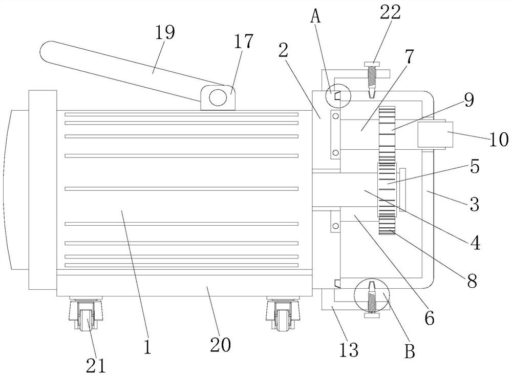
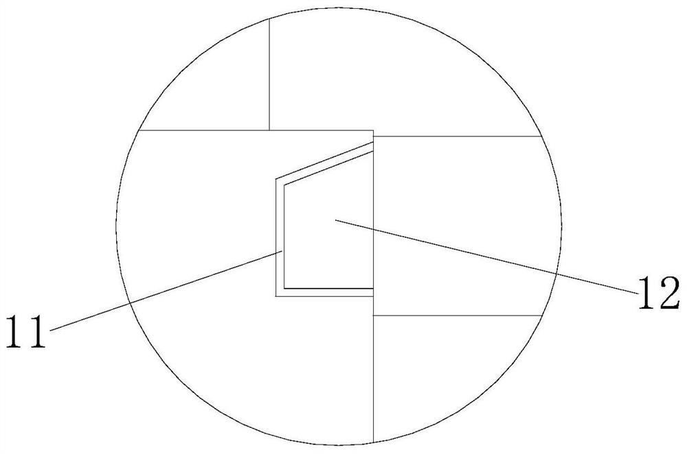
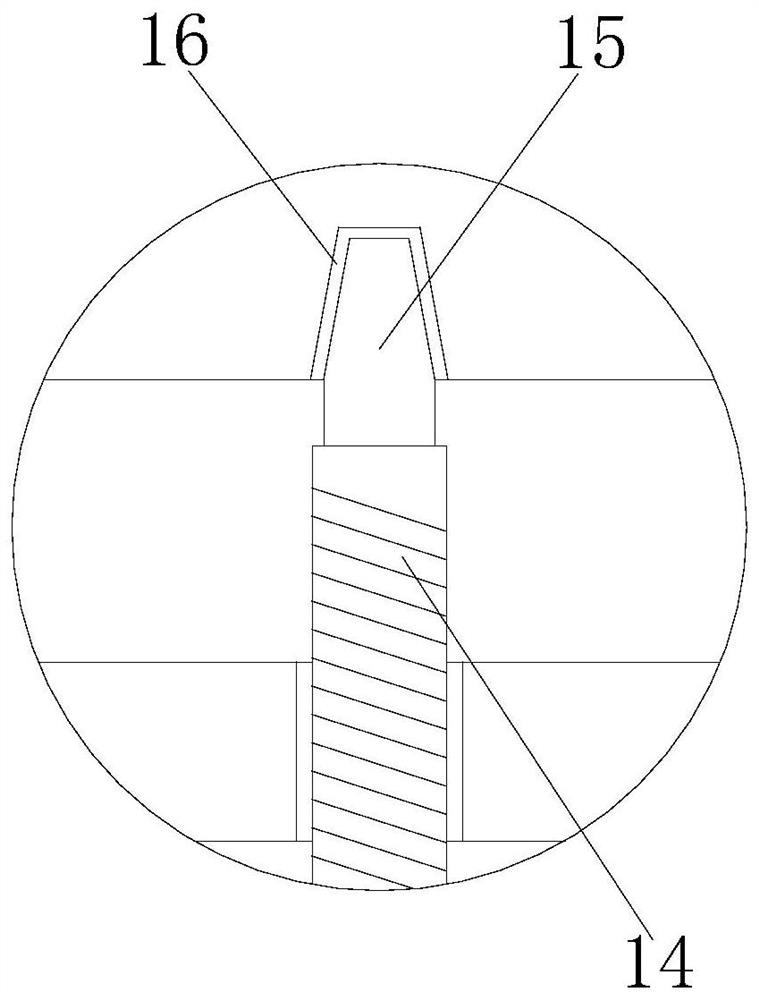
[0022] see Figure 1-Figure 5 , the present invention provides a DC deceleration motor with multi-stage reduction gears, comprising a body 1, one side of the body 1 is fixedly connected with an installation end cover 2, and one side of the installation end cover 2 is provided with a gear box 3, the output of the body 1 The end is fixedly connected with a first rotating shaft 4, the outer surface of the first rotating shaft 4 is fixedly connected with a gear 5,...


PUM


Abstract

The invention discloses a direct-current speed reduction motor with multiple stages of speed reduction gears. The direct-current gear motor comprises a motor body, one side of the motor body is fixedly connected with a mounting end cover, one side of the mounting end cover is provided with a gear box, the output end of the motor body is fixedly connected with a first rotating shaft, and the outersurface of the first rotating shaft is fixedly connected with a gear; and a second rotating shaft and a third rotating shaft are rotatably connected to one side of the mounting end cover, a first reduction gear is fixedly connected to the outer surface of the second rotating shaft, the gear is engaged with the first reduction gear, and a second reduction gear is fixedly connected to the outer surface of the third rotating shaft. According to the direct-current speed reduction motor with the multi-stage speed reduction gears, by arranging a lifting ring, when the speed reduction motor needs tobe moved, the speed reduction motor can be lifted through the lifting ring, meanwhile, a set of universal wheels are arranged, so that the motor replaces carrying with sliding, output of labor force is reduced, and the speed reduction motor becomes diversified in the moving process.

Description

technical field [0001] The invention belongs to the technical field of reduction motors, and in particular relates to a DC reduction motor with multi-stage reduction gears. Background technique [0002] A motor is an electromagnetic device that converts or transmits electrical energy according to the law of electromagnetic induction, or converts one form of electrical energy into another form of electrical energy. A motor converts electrical energy into mechanical energy (commonly known as a motor), and a generator converts mechanical energy into electrical energy. Its main function is to generate driving torque as a power source for electrical appliances or various machinery. According to the type of working power supply, it can be divided into DC motor and AC motor. [0003] The DC deceleration motor is also a kind of motor. It is achieved by multi-stage reduction gears with transmission to achieve the effect of deceleration. The existing DC deceleration motors have gear...

Claims


Application Information

Patent Timeline
Patent Type & Authority Applications(China)
IPC IPC(8): H02K7/116H02K5/04H02K5/22F16H1/22F16H57/023F16M3/00
CPCF16H1/22F16H57/023F16M3/00H02K5/04H02K5/22H02K7/116
Inventor 环剑斌刘乐俊高明江陆震海丁金华封正新陈静宇徐志刚
Owner JIANGSU SANJIANG DISHENG MOTOR CO LTD
Why Eureka
Try Eureka